Rear panel, Panel descriptions – Roland VR-6HD Direct Streaming AV Mixer User Manual
Page 7
7
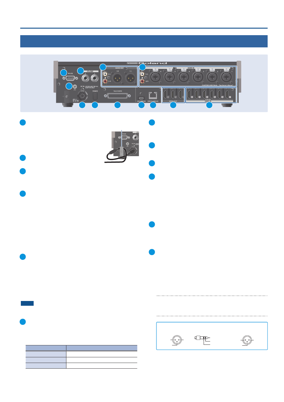
Panel Descriptions
1
DC IN jack
Connect the included AC adaptor to this jack.
* Use the cord hook to secure the cord of the AC
adaptor as shown in the illustration.
If you have trouble running the cord through,
loosen the screw a little on the cord hook.
2
[POWER] switch
Turns the power on/off.
3
TALLY/GPIO connector
Use this to connect to devices that have a tally indicator feature,
or to connect to devices that have a control signal input/output
function.
4
USB STREAM connector (USB Type-C
®
)
¹
Outputs the audio and video to your computer. This is also used to
input audio played on your computer to the VR-6HD.
¹
Use the dedicated software to remotely control the VR-6HD from a
computer or iPad that is connected.
* If you are outputting HD video via USB, connect this to a USB 3.0 port
of your computer.
* Do not use a USB cable that is designed only for charging a device.
Charge-only cables cannot transmit data.
* If you connect via an extension cable or a USB hub, the computer
might not recognize the VR-6HD.
5
DIRECT STREAM port
¹
Connect this port to a network device for livestreaming.
¹
Lets you remotely control the VR-6HD by using terminal software, etc.
¹
Use the dedicated software to remotely control the VR-6HD from a
computer or iPad that is connected.
¹
Use the VR-6HD to remotely control a camera that is connected.
¹
Displays a tally on your iOS or Android device connected to the
network (this is the “smart tally” function).
NOTE
As this port supports GbE, use a LAN cable with a CAT5e
specification or better.
6
VIDEO OUT 1–3 connectors
These connectors are for video output. Use the connectors that
are appropriate for the connected devices.
You can change the video bus assignment for each connector.
With the factory settings, the bus assignments are as follows.
connector
Bus
VIDEO OUT 1
PROGRAM (final output video)
VIDEO OUT 2
PREVIEW (preview output video)
VIDEO OUT 3
MULTI-VIEW
7
VIDEO IN 1–6 connectors
These connectors are for video input. Use the connectors that are
appropriate for the connected devices.
The input format is detected automatically.
8
RS-232 connector
You can connect this to a computer equipped with an RS-232
connector to remotely control the VR-6HD.
9
Ground terminal
Connect this to an external earth or ground, if necessary.
10
CTL/EXP 1, 2 jacks
You can connect a footswitch (such as a BOSS FS-6, sold
separately) or expression pedal (such as the EV-5, sold separately)
to this jack. Use this when you want to switch between video
using your foot.
* Use only the specified expression pedal (Roland EV-5, EV-30, BOSS FV-
500L/FV-500H; sold separately). Connecting expression pedals made
by third-party manufacturers may cause this unit to malfunction.
11
AUDIO OUT (XLR, RCA) jacks
These jacks output audio. Use the jacks that are appropriate for
the connected devices.
For each jack, you can change the audio bus (MAIN, AUX 1, AUX 2,
MONITOR) that is assigned for output from that jack.
12
AUDIO IN 1–6 (XLR/TRS) jacks
Use this connector for audio input. Connect mic or line-level
analog audio equipment here.
*
About phantom power
You can supply phantom power (+48 V) from the AUDIO IN 1–6 jacks
(XLR). This should be switched on for condenser mics that require
phantom power.
[MENU] button
Ó
“AUDIO”
Ó
“INPUT”
Ó
“AUDIO IN 1” – “AUDIO IN 6”, and
set “PHANTOM +48V” to “ON”.
AUDIO IN 7/L, 8/R (LINE IN) jacks
Use this connector for audio input. Connect analog audio
equipment such as an audio mixer here.
2: HOT
1: GND
3: COLD
1: GND
2: HOT
3: COLD
TIP: HOT
RING: COLD
SLEEVE: GND
Pin assignment of AUDIO IN 1–6 (XLR/TRS)
Pin assignment of
AUDIO OUT jack (XLR)
Cord hook
Rear Panel
* To prevent malfunction and equipment failure, always turn down the volume, and turn off all the units before making any connections.
3
10
4
1
2
5
8
6
7
9
11
12