Sony Underwater Housing for Select RX100-Series Cameras User Manual
Page 29
29
adjusting receiver and antenna settings so that “RF” does
not light yellow.
f
QL (signal quality level) meter
Indicates the quality of the received data in a meter.
This meter allows you to monitor quality deterioration of
received signals caused by reduced RF signal reception
sensitivity that may occur when the receiver is too far from
the transmitter or when there is signal interference.
“QL” on the left side of the graph lights up red when the
audio data quality is low.
g
Transmitter name
Indicates the name of the transmitter according to the meta
data that the receiver receives from that transmitter.
h
Output channel display
Displays the audio output destination of the receiver.
In normal operation, channel 1 is output from OUT 1, and
channel 2 is output from OUT 2.
When the OUTPUT SWAP setting is enabled, channel 1 is
output from OUT 2, and channel 2 is output from OUT 1.
The settings are also highlighted on the display.
OUTPUT SWAP is available only on the DWR-R03D
version 1.20 or later.
i
Audio output control/indicator
Indicates the status of audio output for the receiver channel.
Clicking the icon toggles the status of audio output.
: Audio output is enabled. Clicking the icon will enable
muting of the audio output.
: Audio output muting is enabled. Clicking the icon
will disable muting of the audio output.
This setting can only be changed if the [Individual muting/
unmuting] checkbox is selected in the [Display settings]
window.
For details, see “[Display settings] Window” on page 56.
j
AF/PEAK (audio input/peak) level meter/indicator
Indicates the level of audio signal input to the transmitter
according to 32 levels. When a signal exceeding the peak
audio level is input, “AF/PEAK” appears to the right of the
level meter.
k
Battery condition display
The display varies depending on the transmitter model.
• When receiving radio waves from models other than the
DWT-B03R digital wireless transmitter, this indicates
the remaining battery charge of the transmitter in 8 levels
based on metadata received by the receiver from the
transmitter. When the remaining charge is low, the
battery icon turns red.
• When receiving radio waves from the DWT-B03R
digital wireless transmitter, this functions according to
the BATTERY REMAIN setting of the transmitter.
When set to ICON:
Indicates the remaining battery
charge of the transmitter in 8 levels based on metadata
received by the receiver from the transmitter. When the
remaining charge is low, the battery icon turns red.
When set to PERCENT:
Indicates the remaining
battery charge of the transmitter as a percentage based on
metadata received by the receiver from the transmitter.
When the remaining charge is low, the battery icon turns
red.
When set to TIME:
Indicates the remaining operating
time of the transmitter based on metadata received by the
receiver from the transmitter.
l
RF transmission power display
Indicates the transmission power setting of the transmitter
based on metadata received from the transmitter.
H
: Transmission power is 50 mW, 25 mW, or 10 mW
M
: Transmission power is 10 mW
L
: Transmission power is 1 mW or 2 mW
m
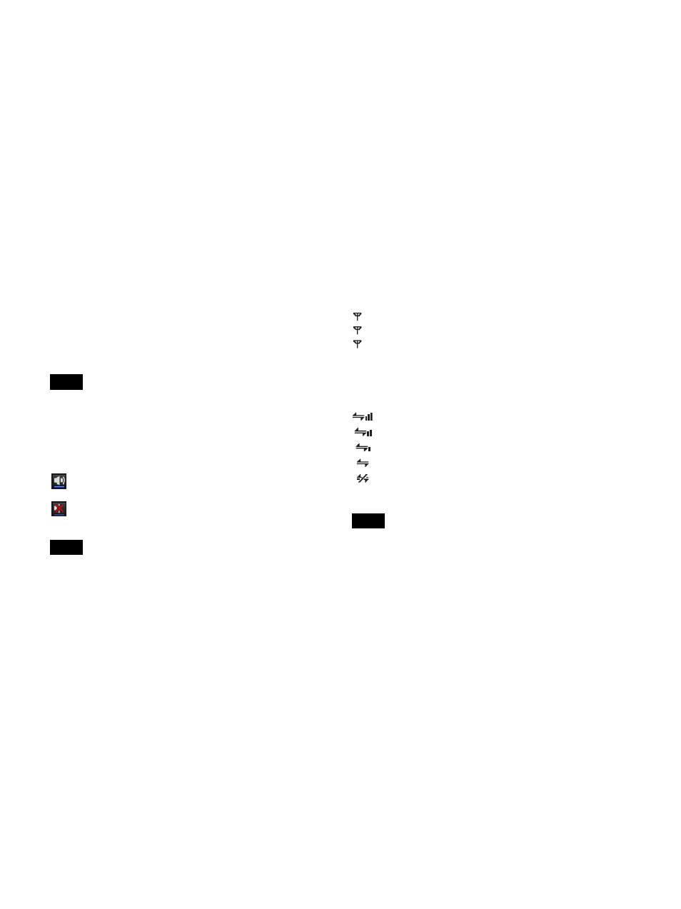
Wireless remote control condition display
Indicates the communication status of the paired
transmitter according to four levels.
This icon does not appear when the RF REMOTE function
on the receiver is turned off.
n
Digital output synchronization display
Indicates the synchronization status of the output signal
from the DIGITAL OUT connector of the receiver.
INT
: The output signal is synchronized to the internal
clock.
EXT
: The output signal is synchronized to the signal input
from the WORD SYNC IN connector.
o
Auto Frequency change status display
Displays the status of the receiver’s AUTO FREQ
CHANGE setting.
HOST
: Displayed when the receiver is operating as the
HOST. It scans the RF spectrum for a good frequency for
use by a CLIENT.
CLIENT
: Displayed when the receiver finds the HOST
and is operating as a CLIENT. Depending on the RF
environment of the transmitter, the frequency
automatically switches to the viable frequency detected by
the HOST.
Note
Note
: Good transmission
: Somewhat good transmission
: Somewhat poor transmission
: Poor transmission
(red indication): Unable to communicate with paired
transmitter
Note