Maintenance – Beisler 1282-4 User Manual
Page 42
- 13 -
Closing Seam Machine 1282-4 Working Instructions
Beisler Automated Sewing Equipment
C.5
Maintenance
Transport unit toothed belt replacement:
The transport unit consistst of three units that are each
driven by a toothed belt:
•
Stepper motor toothed belt,
•
puller toothed belt,
•
roller unit toothed belt.
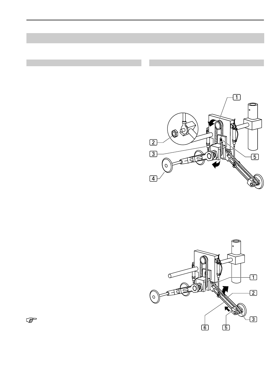
Stepper motor toothed belt replacement:
1. Lower transport unit manually onto workplate (see
Section D.2.1, Program control).
2. Switch machine off.
3. Fig. 8: Release belt tension by removing fixing screw
5
of stepper motor mounting plate.
4. Lift toothed belt up from stepper motor pulley
1
and
then from roller unit
4
. For this, the pressure cylin-
der
3
must be removed from the lower mounting. Re-
move retaining nut
2
and pull scew off the shaft.
5. To install, guide toothed belt over transport pulley lin-
kage and position into shaft drive pulley, then into the
stepper motor drive pulley.
6. To pretension the toothed belt, push plate with step-
per motor down and tighten fixing screw. In case of cor-
rect tensioning, it must be possible to depress the
center of the belt approx 10 mm until counterpressu-
re is felt.
7. Tighten fixing screw
5
.
Puller toothed belt replacement:
1. Lower transport unit manually onto workplate (see
Section D.2.1, Programming Instructions).
2. Switch machine off.
3. Fig. 9: Slacken toothed belt, remove grub screw
5
at the bearing and push bearing up on spacer
shaft
6
.
4. Lift toothed belt up from drive pulley
1
and from the
two rollers
7
and
4
and remove.
5. Install toothed belt to idle roller, then to drive pulley.
6. To pretension the toothed belt, push bearing downward
on spacer shaft and tighten threaded pin. In case of
correct tensioning, it must be possible to depress the
center of the belt
2
approx 10 mm until counter-
pressure is felt.
NOTE - Transport roller alignment!
After toothed belt replacement, the distance between the
puller transport rollers and the working plate must be rea-
ligned (see Section C.5.5).
Fig. 8/9
Fig. 8
Fig. 9