Maintenance – Beisler 1282-4 User Manual
Page 53
Closing Seam Machine 1282-4 Working Instructions
- 24 -
Beisler Automated Sewing Equipment
C.5
Maintenance
Fig. 20
Fig. 20
C.5.5 Machine set-up
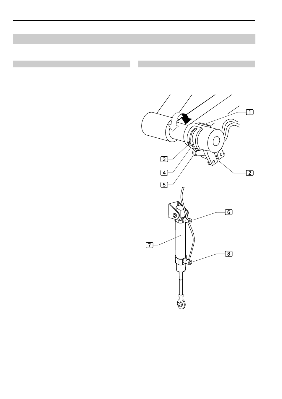
Adjusting the stacker motion:
The motion of the individual stacker linkages is control-
led by the microswitch
2
and by the speed of the pres-
sure cylinder
7
.
To change the start or end of a motion stage, either the
start knop
4
or of the finishing knop
1
is repositioned
on the linkage.
To control the speed of the motion, the throttles
6
and
8
at the pressure cylinders are repositioned.
Setting the knop positions:
1. Loosen knop fixing screw
3
.
2. Reposition knop
4
or
1
.
3. Tighten knop fixing screw.
Setting the motion speed:
1. To change the speed of the forward motion, rotate the
adjusting scew of throttle
7
.
2. To change the speed of the rearward motion, rotate the
adjusting screw of throttle
6
.
3. Directions of rotation:
• To increase speed, rotate throttle in counterclock-
wise direction.
• To reduce speed, rotate throttle in clockwise di-
rection.
Coordination of the motion:
If the microswitch switches early, the linkage strikes. The
start knop must be repositioned to achieve a larger di-
stance to the microswitch contactor.
If the microswitch switches late, the motion is interrupted.
The start knop must be repositioned closer to the micro-
switch contactor
5
.
The positioning of the knops must ensure that the finis-
hing knop stops the motion of a linkage after the start knop
of the next linkage has actuated the microswitch contactor.
The stacker motion consists of six stages:
1. Cylinder 1 pulls up.
2. Microswitch 12 is activated.
• Cylinder 2 lifts.
3. Microswitch 32 is activated.
• Cylinder 3 throws over.
4. Microswitch 11 is activated.
• Linkage return motion starts.
5. Microswitch 22 is activated.
• Cylinder 2 lowers.
6. Microswitch 14 is activated.
• Cylinder 1 moves back to start position.