2 functional description – Comtech EF Data MBT-5003 User Manual
Page 18
MBT-5003 L-Band Up/Down Converter System
Revision 1
Introduction
MN-MBT5003
1–2
1.2
Functional Description
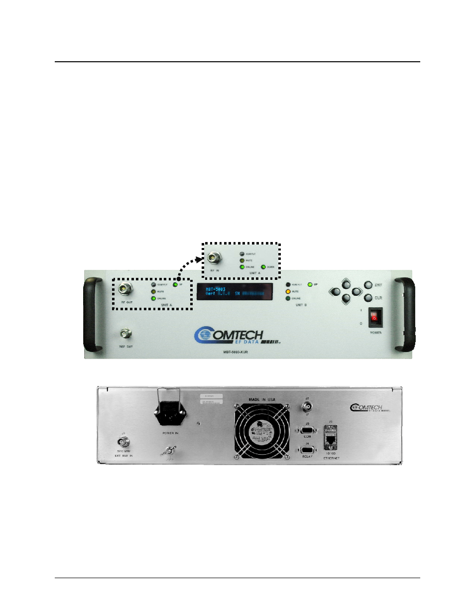
The MBT-5003’s 3RU-high, 19-inch wide chassis is designed for rack mounting into a standard
19-inch equipment rack. As shown in Figure 1-2, handles installed on the front panel facilitate
ease of installation into and removal from the equipment rack.
All operator controls, indicators and displays for local and remote operation are located on the
front panel of the MBT-5003.
External interface connectors are located on the front and rear panels of the MBT-5003 chassis.
External equipment (e.g., a modem) is connected to each internal converter module via a
standard, off-the-shelf coaxial cable. A coaxial cable is also used to connect the output for each
module to RF equipment either at the same location or at the antenna location.
The system contains two diode “OR-ed” internal power supplies for increased reliability, and
microprocessor-based Monitor and Control (M&C) functions. Particular care has been given to
the RF performance of the MBT-5003 to facilitate its successful use in MIL-STD-188-164A
systems.
Figure 1-2. MBT-5003 Front and Rear Panels
On the pages that follow, Figure 1-3 depicts the block diagram for the MBT-5003-XUR L-Band
Up Converter; Figure 1-4 shows the MBT-5003-XDR L-Band Down Converter’s block diagram.
(MBT-5003-XDR Panel Detail)
MBT-5003 Front Panels
MBT-5003 Typical Rear Panel