2 j2 | if connector, type ‘tnc’ female, 3 j3 | com connector (eia-485 interface), db-9f – Comtech EF Data MBT-5003 User Manual
Page 33
MBT-5003 L-Band Up/Down Converter System
Revision 1
External Connectors
MN-MBT5003
3–3
3.2.1.3 RF IN Connector (MBT-5003-XDR only), Type ‘N’ Female
The RF IN connector is a type ‘N’ female coaxial connector provided only on the
MBT-5003-XDR Down Converter front panel. It provides the downconverted RF input
signal for customer use.
3.2.2 Rear Panel Connectors (Typical MBT-5003-XUR / MBT-5003-XDR)
3.2.2.1 J1 | 5/10 MHz EXT REF IN Connector, Type ‘BNC’ Female
The J1 | 5/10 MHz EXT REF IN interface is a type ‘BNC’ female coaxial connector,
used to supply a master reference to the entire chassis. The input signal supplied here by
the user is used for phase-locking the internal 5/10MHz reference oscillator. The
impedance is matched for 50/75
Ω, and requires an input level of 5 ±5 dBm.
3.2.2.2 J2 | IF Connector, Type ‘TNC’ Female
The J2 | IF connector is a type ‘TNC' female coaxial connector. For the
MBT-5003-XUR, it provides the L-Band input signal to be upconverted; for the
MBT-5003-XDR, it provides the L-Band output signal to be downconverted.
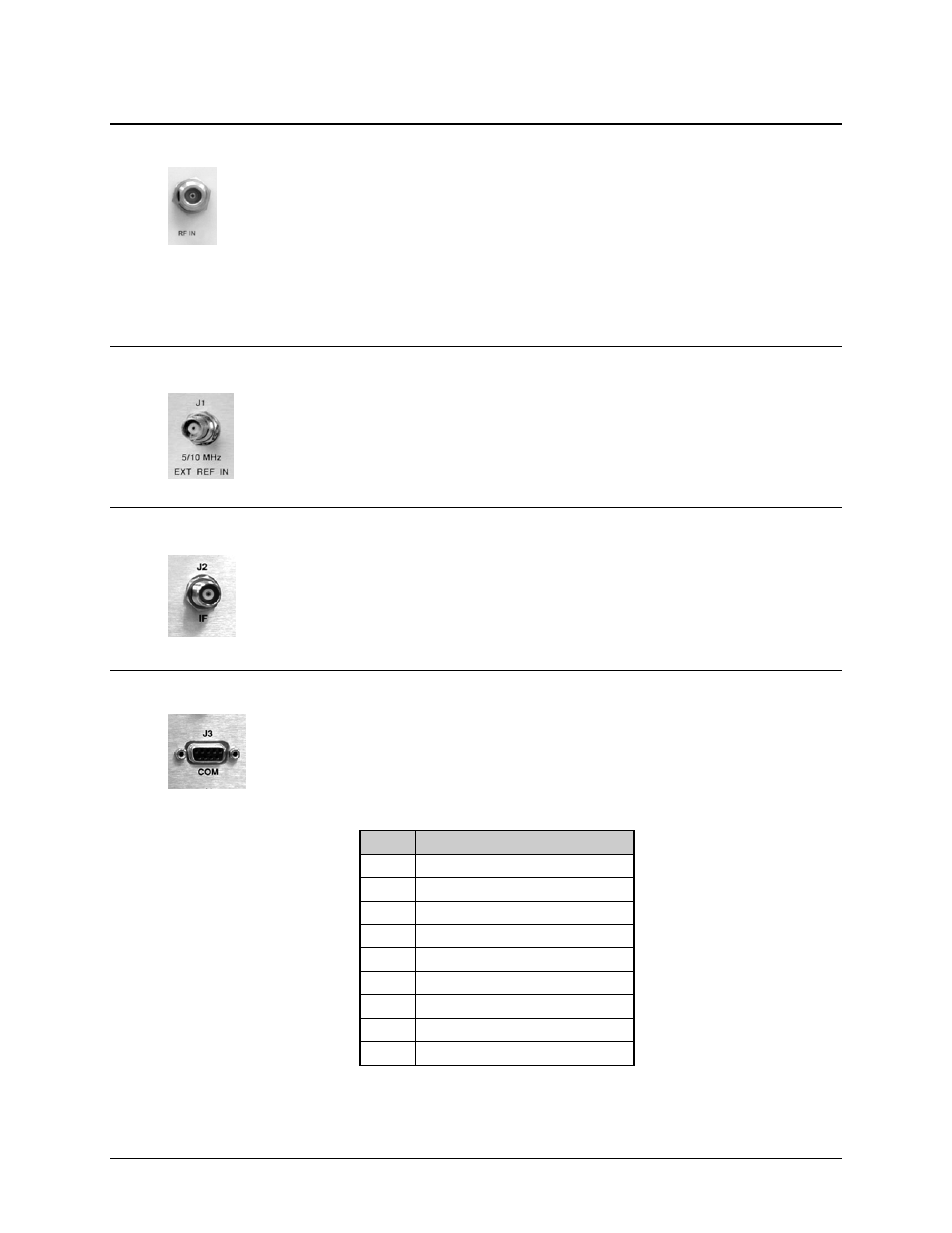
3.2.2.3 J3 | COM Connector (EIA-485 Interface), DB-9F
The J3 | COM EIA-485 4-wire interface is a 9-pin type ‘D’ (DB-9F) connector (the
mating connector is a DB-9M connector). The pinout specifications for EIA-485 are
contained in Table 3-2.
Table 3-2. J3 | COM – EIA-485 (4-Wire) Interface
Pin #
Description
1 +Tx;
Signal
2
3
4
5 GND;
Ground
6
-TX; Signal Complement
7
8 +RX;
Signal
9
-RX; Signal Complement
Note: Tx is the signal which transmits out of the MBT-5003.