Comtech EF Data MBT-5003 User Manual
Page 34
MBT-5003 L-Band Up/Down Converter System
Revision 1
External Connectors
MN-MBT5003
3–4
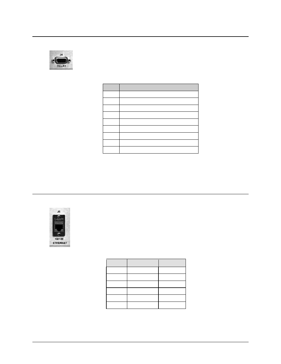
3.2.2.4 J4 | RELAY (Summary Fault Output) Connector, DB-9F
The J4 | RELAY summary fault output interface is a 9-pin type ‘D’ (DB-9F)
connector (the mating connector is a DB-9M connector). The pinout specifications
are contained in Table 3-3.
Table 3-3. J4 | RELAY – Summary Fault Output
Pin #
Description
1 SUMFLT1_NC
2 SUMFLT1_NO
3 SUMFLT2_NC
4 SUMFLT2_NO
5 GND
6 SUMFLT1_COM
7 EXT_FLT_IN#
8 SUMFLT2_COM
9 NC
Notes:
1. Pin 1 to Pin 6: Unit ‘A’ Fault
2. Pin 2 to Pin 6: Unit 'A' OK
3. Pin 3 to Pin 8: Unit ‘B’ Fault
4. Pin 4 to Pin 8: Unit ‘B’ OK
3.2.2.5 J5 | 10/100 Ethernet (M&C 10/100 BaseT Ethernet) Port, (RJ-45)
The J5 | 10/100 ETHERNET port provides a standard RJ-45 female interface for
10/100 BaseT Ethernet M&C (used for management and control via Telnet, HTTP,
and SNMP). It is also used for upgrading MBT-5003 firmware. This CAT5 receptacle
uses a UTP cable to connect to an Ethernet hub, router, switch, PC, etc. The pinout
specifications are contained in Table 3-4.
Table 3-4. J5 | 10/100 ETHERNET – M&C
Pin #
Description
Direction
1 Tx+ Out
2 TX- Out
3 Rx+ In
4 N/A
5 N/A
6 Rx- In