Pl1877a – radio installation, Mitrek consolette – pl1877a single simplex mode – GAI-Tronics MRTI 2000 (No. PL1877A) Microprocessor Radio Telephone Interconnect Installation & Service Manual User Manual
Page 143
137
12/10
PL1877A – Radio Installation
This section covers the installation information for the specific radio models listed below. General
installation instructions not specifically mentioned here are covered in the Installation Considerations
section of this manual.
• Mitrek Consolette
• Flexar Repeater
• MCR100 Repeater
• Maxar 80 Base
• T1600 Series Remote
• MaxTrac 300 Base Station
• Micor RCB Repeater
• MSF5000 Series Base
N
OTE
: If any of the following options are included in this PL1877A set-up, parameter modification as
described in the Parameter Modification Procedures section starting on page 77 may be necessary to
enable or disable a particular function.
Mitrek Consolette – PL1877A Single Simplex Mode
Interconnection between the PL1877A and the base station can be made via the accessory terminal strips
TB1 and TB2 on the rear of the chassis. In most applications, there are several spare terminals available
for special interfacing in addition to the standard function provided. Install the following modification/
additions to the base station using spare screw terminals on TB1 and TB2:
1. RX Detected Audio - Run a wire to DETECTED AUDIO available at solder strip TB4-6 (local
control station only), or TB10-6 (remote control station).
2. PL Detect – Run a wire to SQUELCH DISABLE on the Mitrek transmitter-receiver board.
Set up the PL detect circuit output for “or squelch” operation. (JU1 in, JU2 out on the PL deck for
tone PL; JU5 in, JU4 out for digital PL.) If the radio has a busy light kit, refer to the schematic for
jumper information. If the busy light kit is not present, add a 5.6k ¼ W resistor from SQUELCH
DISABLE to ground.
3. PL Stripping – Run a wire to the CD (code disable) stake pin on the PL deck.
4. Reverse Burst Inhibit – Run a wire to the PL deck as follows: digital PL deck – to E3 stake pin;
tone PL deck – to junction of R18 + R22.
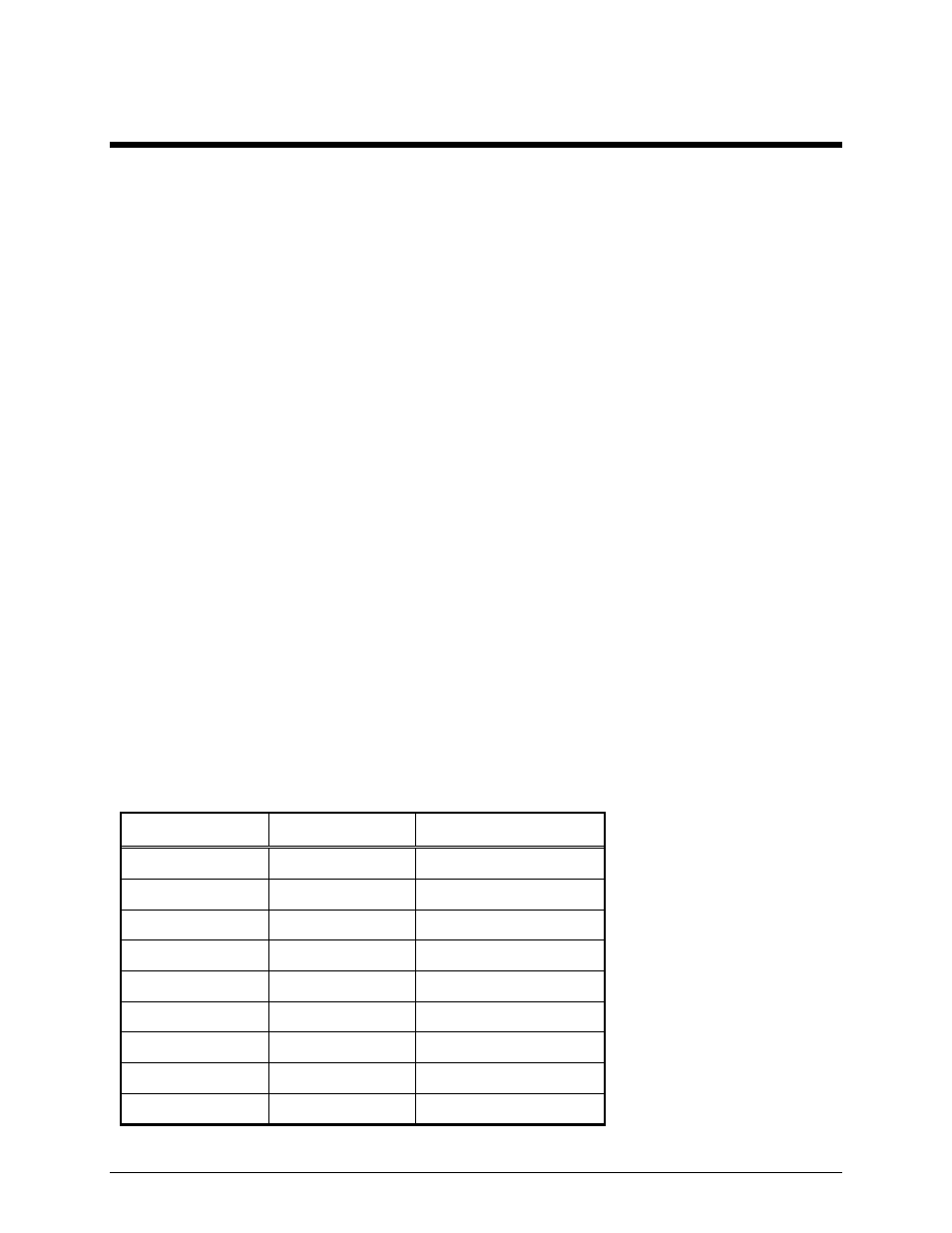
5. Now connect the PL1877A P1 interconnect cable to TB1 and TB2 as follows:
P1 Cable Color To
Function
Red/black Designated
spare
TX PL stripping
Red TB2-4 Ground
Green/black TB2-4
Ground
Orange
Designated spare
Reverse burst inhibit
Green/white
Designated spare
RX detected audio
White TB2-5 PTT
Black
Designated spare
PL detect
Blue/black TB2-6
Mic
low
Blue/white TB2-7
Mic
high