P1 radio connector – GAI-Tronics MRTI 2000 (No. PL1877A) Microprocessor Radio Telephone Interconnect Installation & Service Manual User Manual
Page 18
Installation PL1877A
Microprocessor Radio Telephone Interconnect
12/10 12
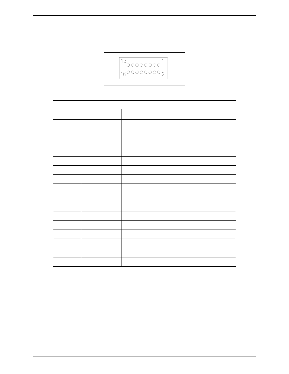
P1 Radio Connector
The 16-pin radio connector (P1) pin designations are shown below. Refer to the applicable section of
this manual for your specific radio for more detailed information on its installation.
Radio Connector Pinout
P1 Radio Connector Pin Chart
Pin No.
Wire Color
Function
1 Red/Black PL
Strip
2
Red
PL Strip Return
3 Orange
Monitor
4 Orange/Black
Monitor
Return
5 White
PTT
6 Green
PTT
Sense
7
White/Black
Data TX (TPL and DPL signal output)
8
Blue White
TX Audio
9
Blue/Black
TX Audio Return
10
Green/White
RX Audio Return
11 Green/Black RX
Audio
12 Black
PL
Detect
13 Blue
Carrier
Detect
14
Black/White
Optional Input #1
15 Red/White Patch
Inhibit
16
Not connected
Optional Input #2
The PL1877A has been designed with several diagnostic tests to assist you in set-up and troubleshooting.
Entry into the diagnostic mode is made by simultaneously pressing the
UP
and
DOWN
buttons.
To step to another test once the diagnostic mode has been entered, press the
PATCH
ON/OFF
button. To
exit, press both the
UP
and
PATCH
ON/OFF
buttons simultaneously.
Each time a new test is selected, a test timer is set to 15 minutes. If this timer reaches zero, the patch
resets itself to idle, ready for normal operation.