Msf 5000 digital base/repeater stations – GAI-Tronics MRTI 2000 (No. PL1877A) Microprocessor Radio Telephone Interconnect Installation & Service Manual User Manual
Page 160
Pl1877A – Radio Installation
PL1877A Microprocessor Radio Telephone Interconnect
12/10 154
All other parameters are programmed as applicable to system requirements. Refer to the “Parameter
Modification Procedure” on page 77 and then the “Level Setting” section on page 17 of this manual.
Level Setting – The remote should be set to provide +8 dBm output measured at the 8-ohm hot output
with any Touch-Code digit from a properly adjusted mobile. Also, refer to “Level Setting” section in this
manual.
NOTE
The line input level to the remote should be adjusted to the minimum level that will
provide satisfactory receive volume (at the knee of compression and no more).
Excessive input sensitivity or too high an adjustment of the receive line input level potentiometer will
result in an increase in effective line noise and/or hum, possibly causing improper operation of the
PL1877A cross lock-out VOX feature. During final tests, a check should be made by setting up the
PL1877A for Test 5 (refer to “Internal Diagnostics” section of this manual) and ascertain the
RADIO
BUSY
LED is extinguished when not receiving a mobile signal and is illuminated with the presence of
receive audio.
MSF 5000 Digital Base/Repeater Stations
Installation of the PL1877A to the MSF 5000 digital station requires the MSF 5000 Cable Kit, Part No.
M2000-MSF5000-CBL. The station must be programmed for phone patch operation using MSF 5000
Radio Service Software (available through Motorola Service Stations). Connect the signal cable to
connector P802 on the MSF 5000 station control module. Connect the dc power cable to the screw
terminal strip on the station power supply.
Earth Ground - Run the supplied #12 black ground wire from the PL1877A GND terminal to the base
station chassis. This wire must be as short as practical, not coiled, and connected securely to the base
station chassis.
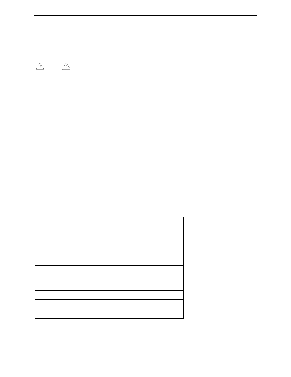
Required Parameter Settings - Using the Parameters Modification Procedure detailed in this manual set
the following parameters:
Parameter Setting
1
0 (flat source audio)
2
1, JU202 OUT (mid-level)
3
1 (external logic level carrier detect)
4
0 (carrier detect input is active low)
5
0 (internal squelch for carrier detect)
6
0 (no PL detect input required)
1 (PL detect input required)
7
0 (PL detect is active low)
9
0 (half duplex)
10
0 (active low PTT sense input)