Maxtrac 300/gm300 base station – GAI-Tronics MRTI 2000 (No. PL1877A) Microprocessor Radio Telephone Interconnect Installation & Service Manual User Manual
Page 161
PL1877A Microprocessor Radio Telephone Interconnect
PL1877A – Radio Installation
155
12/10
MAXTRAC 300/GM300 Base Station
Enhanced VOX Mode – Installation of the PL1877A to the MaxTrac 300 radio requires the
MaxTrac/GM300 Cable Kit, Part No. M2000-MAX-CBL. The radio must be programmed for phone
patch operation using Radio Service Software (available through Motorola Service Stations).
If the PL1877A is to be dc-powered, connect the dc power cable from the patch to the base station power
supply. If the optional ac transformer and cable is to be used, install the ac power connector into the 5-
pin DIN connector (
DC
PWR
), on the rear panel of the PL1877A.
Earth Ground – Run the supplied #12 black ground wire from the PL1877A ground terminal to the base
station chassis. This wire must be as short as practical, not coiled, and connected securely to the base
station chassis.
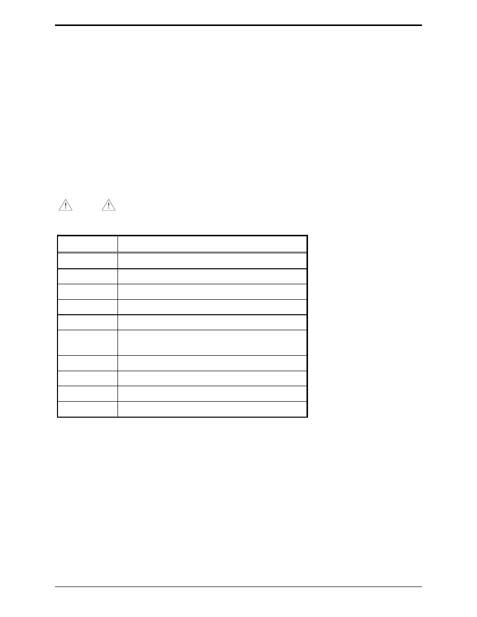
Required Parameter Settings – Using the Parameter Modification Procedure detailed in this manual,
set the following parameters:
NOTE
With the parameter settings listed below, the radio must be internally jumpered to
provide de-emphasized muted audio, JU551 must be in the B position.
Parameter Setting
1
0 (flat source audio)
2
1, JU202 OUT (mid-level audio)
3
1 (external logic level carrier detect)
4
0 (carrier detect input is active low)
5
0 (internal squelch for carrier detect)
6
0 (no PL detect input required)
1 (PL detect input required)
7
0 (PL detect is active low)
9 1
(simplex)
10
0 (active low PTT sense input)
70
1 (enhanced VOX, requires Enhanced VOX option)