Connections, Control connections, 1 − introduction – Teac SS-CDR1 User Manual
Page 10
1 − Introduction
10
TASCAM SS-CDR1
The pinouts of the
CONTROL I/O
(
PARALLEL
) terminal
on the rear panel (see “Rear panel” on page 13) are:
Pin
Function
IN/OUT
1
GND
—
2
Play/Flash 1
In
3
Stop/Flash 2
In
4
Record/Flash 3
In
5
≤
(Next)/Flash 4
In
6
µ
(Previous)/Flash 5
In
7
Flash Load
In
8
Fader Start
In
9
Flash Tally
Out
10
Ready Tally
Out
11
Record Tally
Out
12
Stop Tally
Out
13
Play Tally
Out
14
Remote Select*
2
In
15
Ready/Flash 6
In
16
Call/Flash 7
In
17
Auto Cue/Flash 8
In
18
Auto Ready/Flash 9
In
19
Pitch/Flash 10
In
20
Flash Page*
3
In
21
EOM Tally
Out
22
CF Tally
Out
23
—
—
24
CD Tally
Out
25
+5V*
1
—
In: External command reception active flow
(operates at 30 ms or longer of ground)
Out: transport status by open drain
Indication signal (maximum voltage 50 V, maximum current
50 mA)
*1 Maximum supplied current is 50 mA.
*2 Pin 14 (Remote Select)
When this pin is high, the input pins for which the above
table lists two commands separated by a “/” (pins 2–6
and 15–19) will perform the first-listed function, and can
be used as conventional parallel controllers.
When this pin is low, the above-listed input pins will func-
tion as flash start keys.
*3 Pin 20 (Flash Page)
When pin 14 (Remote Select) is low, the assigned tracks
will be as follows according to the high/low state of pin
20.
#14
#20
Flash-start status
Low
High
1–10
Low
Low
11–20
Tall signals are open collector, with a maximum current
of 50 mA. Input signals are active when low (ground)
for ≥ 30 ms.
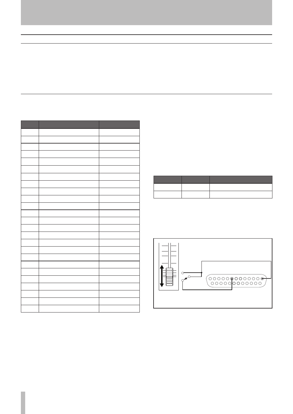
A fader start/stop control should be wired according to the
following schematic:
START
STOP
Pin 1
FADER START
Pin 8
GND
PARALLEL
Control connections
The following should be noted when you connect the unit
to other equipment.
It is possible to connect the unit’s
DIGITAL COAXIAL IN
,
and balanced or unbalanced
ANALOG INs (L, R)
to other
equipment at the same time. However, the unit can receive
signals from only one input at a time. Currently selected
input jack is shown on the display.
Audio signals output from the unit are output from the
balanced or unbalanced
ANALOG OUT
jacks, as well as
from the
DIGITAL COAXIAL OUT
connector simultane-
ously (but not from the digital output in stop mode).
Connections