Rear panel, Remote control unit (rc-ss1), Rear panel remote control unit (rc-ss1) – Teac SS-CDR1 User Manual
Page 13: 2 − controls and connectors
2 − Controls and connectors
TASCAM SS-CDR1
13
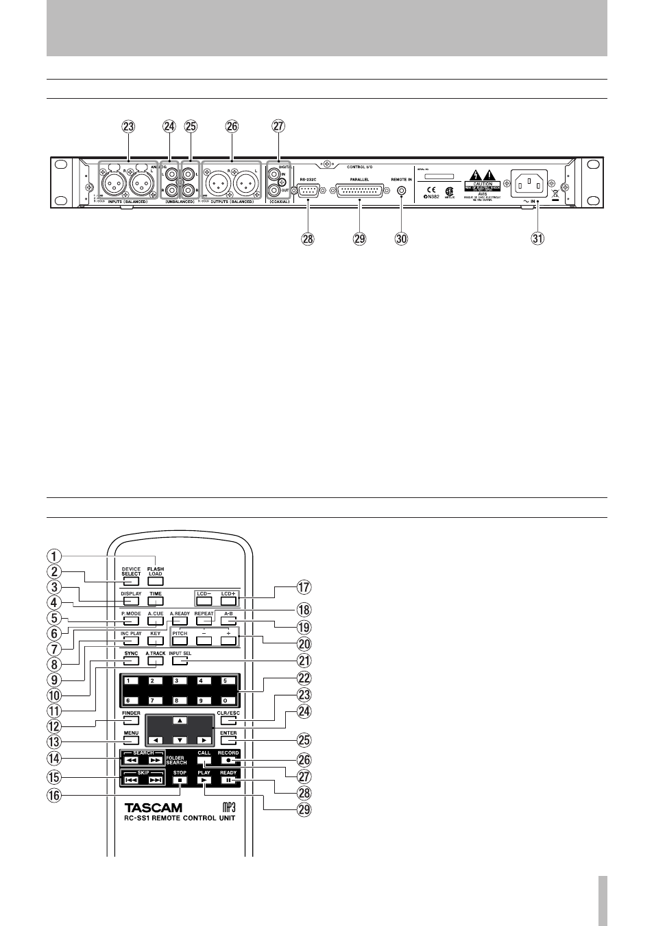
Remote control unit (RC-SS1)
1
FLASH LOAD key
This loads the registered tracks in
preparation for Flash Start. When the tracks have been
loaded, the display will indicate
FLASH
(see “Flash Start
function” on page 36).
2
DEVICE SELECT key
This key has the same function
as the front panel
SELECT
key.
3
DISPLAY key
This has the same function as the front
panel
DISPLAY (INFO)
key.
4
TIME key
If you press this key while in the home screen,
the time display mode of the recorder will change (see
“Switching the playback time display mode” on page 28,
“Switching the recording time display mode” on page
44).
5
P.MODE key
This switches the playback mode be-
tween CONTINUE (normal consecutive playback),
SINGLE (play one song), PROGRAM (program play-
back), and RANDOM (random playback) (see “Play-
back modes” on page 27).
6
A. CUE key
This turns the Auto Cue function on/off
(see “Auto Cue function” on page 32).
Rear panel
d
ANALOG INPUTS L/R (BALANCED) jacks
These are
analog input jacks (XLR balanced).
The nominal input level is +4 dBu.
Pin wiring: pin 1 = ground, pin 2 = hot, pin 3 = cold.
f
ANALOG INPUTS L/R (UNBALANCED) jacks
These
are analog input jacks (RCA pin jacks).
The nominal input level is -10 dBV.
g
ANALOG OUTPUTS L/R (UNBALANCED) jacks
These are analog output jacks (RCA pin jacks).
The nominal output level is -10 dBV.
h
ANALOG OUTPUTS L/R (BALANCED) plugs
These
are analog output plugs (XLR balanced).
The nominal output level is +4 dBu.
Pin wiring: pin 1 = ground, pin 2 = hot, pin 3 = cold.
j
DIGITAL IN/OUT (COAXIAL) jacks
These are digital in-
put/output jacks compatible with IEC-60958 (S/PDIF).
k
CONTROL I/O (RS-232C) connector
This is a D-sub
9-pin RS-232C connector for control I/O. You can
connect it to an external computer or other device (see
“Using the RS-232C connector” on page 79).
l
CONTROL I/O (PARALLEL) connector
This is a D-
sub 25-pin parallel connector for control I/O. You can
connect it to an external controller. For the pin wiring,
refer to “Control connection” on page 10.
;
REMOTE IN connector
Connect the RC-SS1 dedi-
cated remote here.
z
AC IN connector
Connect the included power cable
here.