More about timing, More about timing -3 – Verilink AS4000 (34-00244) Product Manual User Manual
Page 103
Quad Port Sync Data Module
Verilink AS4000 User Manual
6-3
More About
Timing
The following applies to the Quad DS-1 Sync Data module as well as
synchronous serial interfaces in general.
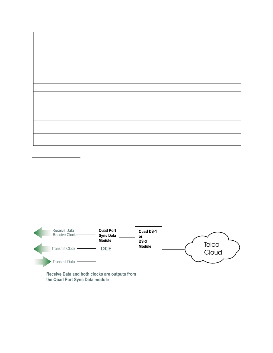
DCE Outputs Clock
Data Communications Equipment (DCE) outputs clock. Data
Terminal Equipment (DTE) accepts clock as an input. The AS4000
Quad Port Sync Data module always functions as DCE, so it always
outputs clocks. The connected DTE monitors the transmit clock
signal and presents data to be sent to the far-end (transmit data) at
the rate of the transmit clock signal. See
Figure 6-3 DCE Outputs Clock
Int/Ext Timing
Int/Ext is recommended if the attached user DTE cable exceeds 10
feet in length and the customer data rate exceeds 224 kbit/s. In
order for the Int/Ext selection to work, the DTE must wrap the
Clock
Ideally, the DTE presents transmit data so that the negative-going transition of
transmit clock occurs in the middle of each bit. On long cables when transmit clock is
sent from the DCE device to clock data from the DTE device, the data arrives delayed
with respect to transmit clock due to the round trip cable delay. When the delay is
such that the negative-going clock transition occurs at about the time of transition
from one data bit to the next—sampling errors will occur. The Inv option will correct
this condition by causing the Quad Port Sync Data module to delay its sampling 180
degrees of a clock cycle—until the positive-going clock transition.
Initially choose Normal. If frequent errors occur at the port, try Inverted and check
results at the far-end DTE device.
Interface
The interface options are V.35, RS 530/422 and RS-232.
V.54 Loop
When enabled, this port will respond to receipt of a remote digital loop command
arriving from the port of the far-end Quad Port Sync Data module (or industry standard
DSU). When disabled, it will not respond to any remote loop command.
Connect event
Enables or disables the connnection or disconnection of a port to be recorded in the
System Event menu.
Port status
This field determines the status of the port. The status will either be in service or out
of service.
Cascade LEDs
s
s
s
w
w
w
when I
hen I
hen I
hen Id
d
d
dle
le
le
le
When selected, any unused ports will display a moving pattern of blinking LEDs.