Dc power connections, Installing application modules, Rear interface card – Verilink AS4000 (34-00244) Product Manual User Manual
Page 40: Dc power connections -4, Installing application modules -4, Rear interface card -4
Hardware Installation
3-4
Verilink AS4000 User Manual
WARNING
Verilink AC power supplies require a three-prong grounded receptacle.
Do not use an adapter to connect these plugs to an ungrounded
receptacle.
DC Power
Connections
Use the following procedures to connect the DC power to the
AS4000.
NOTE: When powering AS4000 from a 48V battery, use two separate
fuse panels or a fuse panel with redundant (A and B) fuse
positions.
Connect the shelf to the fuse panel by doing the following:
1. Insert the negative wire into the connector labeled -48V.
2. Connect the positive wire to the terminal labeled RTN.
3. Torque connector wire set screws to 4.5 to 8.0 inch lb (0.5 Nm
to 0.9 Nm).
Installing Application Modules
This section installs the application module into an AS4011 and a
AS4004. Refer to the system configuration worksheet to match the
rear interface card to the corresponding front application card.
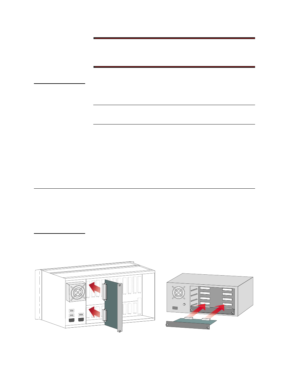
Rear Interface
Card
illustrates a AS4000 rear interface card installation. To
install the rear interface card, do the following:
Figure 3-2 Rear Connector Card Installation
Midplane
Midplane