Verilink AS4000 (34-00244) Product Manual User Manual
Page 104
Quad Port Sync Data Module
6-4
Verilink AS4000 User Manual
transmit clock signal back towards the Quad Port Sync Data module
on the optional third pair of clock leads (TT in EIA-530, SCTE in
V.35, XTC in RS-232).
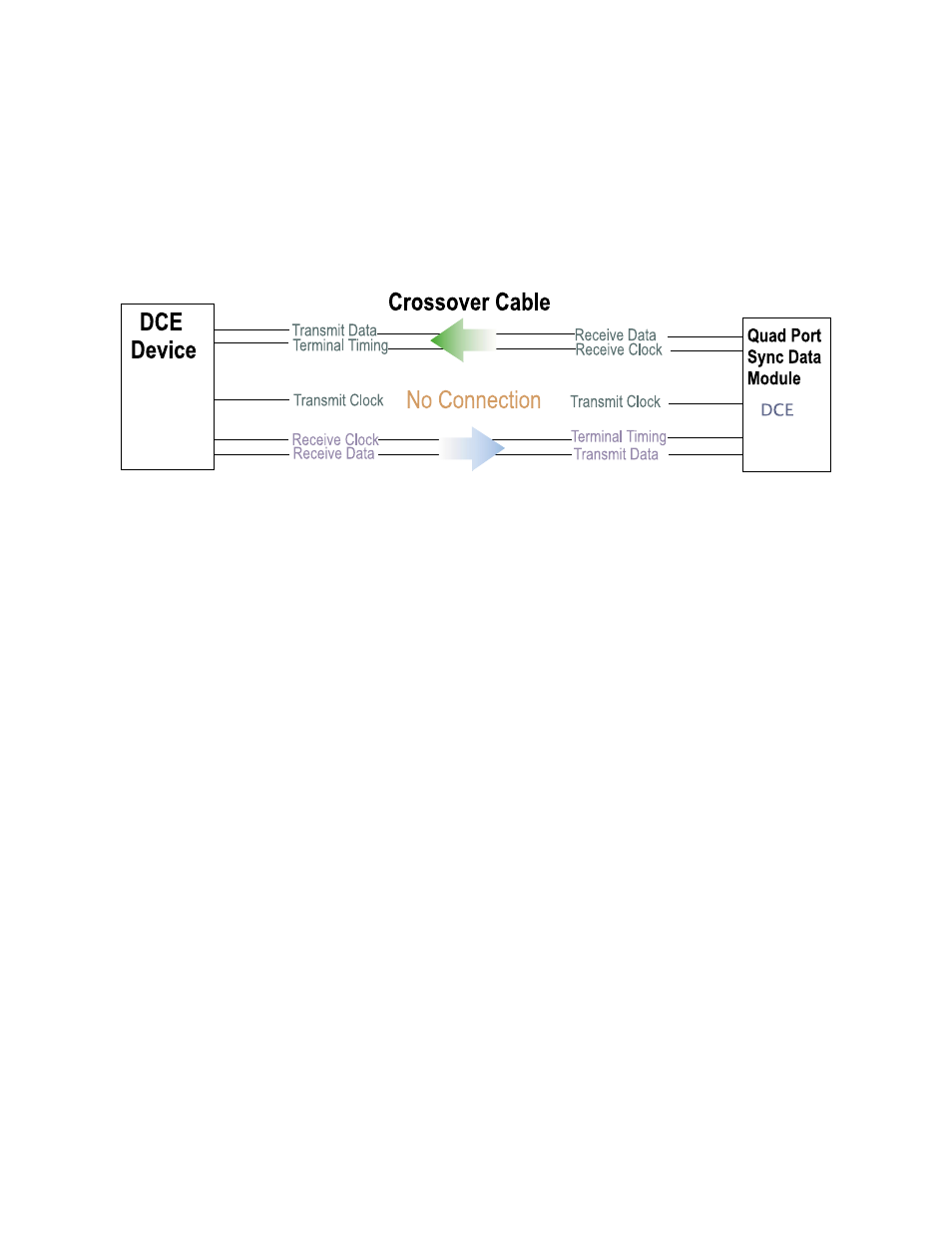
Crossover Timing
When two Data Communications Equipment (DCE) devices are
connected together in order to extend a circuit to a third location, a
crossover cable must be used.
Figure 6-4 Crossover Cable
On the AS4000 Quad Port Sync Data, Int/Ext must be used. The
attached equipment is also DCE. The attached DCE must accept the
Receive Clock provided by the AS4000 data port as an input on its
terminal timing pair. This clock is used as the transmit clock of the
locally attached DCE device . The remote DCE must be loop timed
to achieve the required timing lock with the AS4000 system clock.
External should be used if the attached equipment is DCE that does
not accept a clock, such as a Digital Dataphone Service (DDS) DSU.
The DSU and the AS4000 system must be locked to the same timing
source (usually network clock).
The external DCE device can provide timing to the AS4000 system
only when it is attached to port 1 and the port is configured as
source clock. Remember that an AS4000 node may have only one
clock source. It may not be desirable to time an entire node from a
single external low data rate circuit.
System Level
Timing
The System Manager module stores the shelf timing table for all
modules within the shelf. Each module uses this shared timing
source. Two backup timing sources are available for the system. If
the timing source fails, the designated backup module
automatically assumes the timing duties.