Mstp configuration example, Network requirements, Configuration procedure – H3C Technologies H3C WX3000 Series Unified Switches User Manual
Page 214
22-45
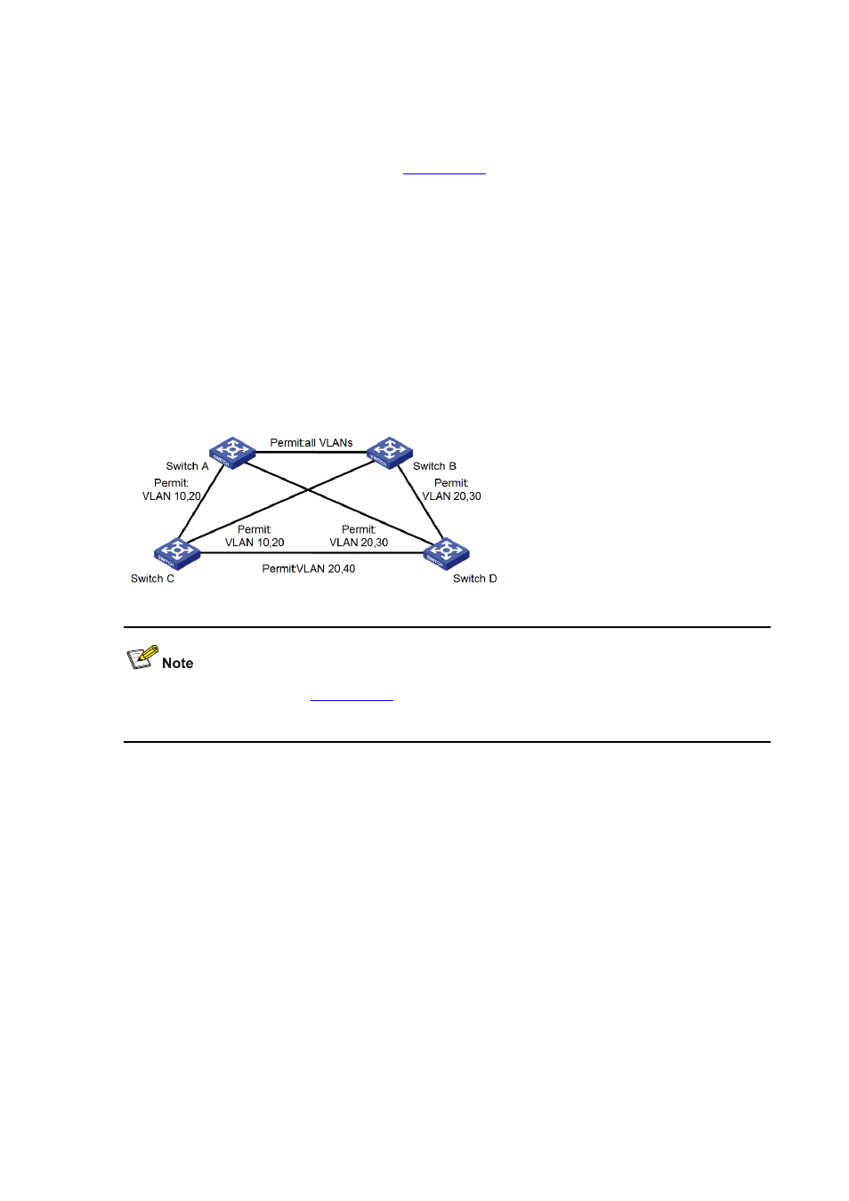
MSTP Configuration Example
Network requirements
Implement MSTP in the network shown in
to enable packets of different VLANs to be
forwarded along different spanning tree instances. The detailed configurations are as follows:
z
All switches in the network belong to the same MST region.
z
Packets of VLAN 10, VLAN 30, VLAN 40, and VLAN 20 are forwarded along spanning tree
instance 1, instance 3, instance 4, and instance 0 respectively.
In this network, Switch A and Switch B operate on the convergence layer; Switch C and Switch D
operate on the access layer. VLAN 10 and VLAN 30 are limited in the convergence layer and VLAN 40
is limited in the access layer. Switch A and Switch B are configured as the root bridges of spanning tree
instance 1 and spanning tree instance 3 respectively. Switch C is configured as the root bridge of
spanning tree instance 4.
Figure 22-10
Network diagram for MSTP configuration
means the corresponding link permits packets of specific
VLANs.
Configuration procedure
1) Configure Switch A
# Enter MST region view.
<SwitchA> system-view
[SwitchA] stp region-configuration
# Configure the region name, VLAN-to-MSTI mapping table, and revision level for the MST region.
[SwitchA-mst-region] region-name example
[SwitchA-mst-region] instance 1 vlan 10
[SwitchA-mst-region] instance 3 vlan 30
[SwitchA-mst-region] instance 4 vlan 40
[SwitchA-mst-region] revision-level 0
# Activate the settings of the MST region manually.
[SwitchA-mst-region] active region-configuration
# Specify Switch A as the root bridge of spanning tree instance 1.
[SwitchA] stp instance 1 root primary