H3C Technologies H3C WX3000 Series Unified Switches User Manual
Page 666
67-5
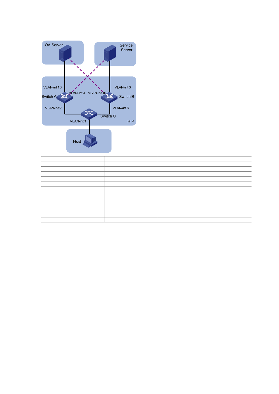
Figure 67-1
Network diagram
Device Interface
IP
address
Switch A
Vlan-int 2
2.2.2.1/8
Vlan-int
3
3.3.3.254/8
Vlan-int
10
1.1.1.254/8
Switch B
Vlan-int 3
3.3.3.253/8
Vlan-int
6
6.6.6.5/8
Vlan-int
10
1.1.1.253/8
Switch C
Vlan-int 1
192.168.0.39/24
Vlan-int
2
2.2.2.2/8
Vlan-int
6
6.6.6.6/8
OA Server
1.1.1.1/32
Service Server
3.3.3.3/32
Host 192.168.0.9/24
Configuration considerations
z
According to the network requirements, select RIP.
z
For the OA server, the main link is between Switch A and Switch C, while the backup link is
between Switch B and Switch C.
z
For the service server, the main link is between Switch B and Switch C, while the backup link is
between Switch A and Switch C.
z
Apply a route policy to control the cost of routes received by Switch C to provide main and backup
links for the services of the OA server and service server.
Configuration procedure
1) Configure Switch A.
# Create VLANs and configure IP addresses for the VLAN interfaces. The configuration procedure is
omitted.
# Configure RIP.
<SwitchA> system-view
[SwitchA] rip
[SwitchA-rip] network 1.0.0.0
[SwitchA-rip] network 2.0.0.0