Configuring ntp broadcast mode, Configuring ntp broadcast mode -17 – H3C Technologies H3C WX3000 Series Unified Switches User Manual
Page 468
46-17
# View the information about the NTP sessions of Device C (you can see that a connection is
established between Device C and Device B).
[DeviceC] display ntp-service sessions
source reference stra reach poll now offset delay disper
*************************************************************************
[1234]3.0.1.32 LOCL 1 95 64 42 -14.3 12.9 2.7
[25]3.0.1.31 127.127.1.0 2 1 64 1 4408.6 38.7 0.0
note: 1 source(master),2 source(peer),3 selected,4 candidate,5 configured
Total associations : 2
Configuring NTP Broadcast Mode
Network requirements
z
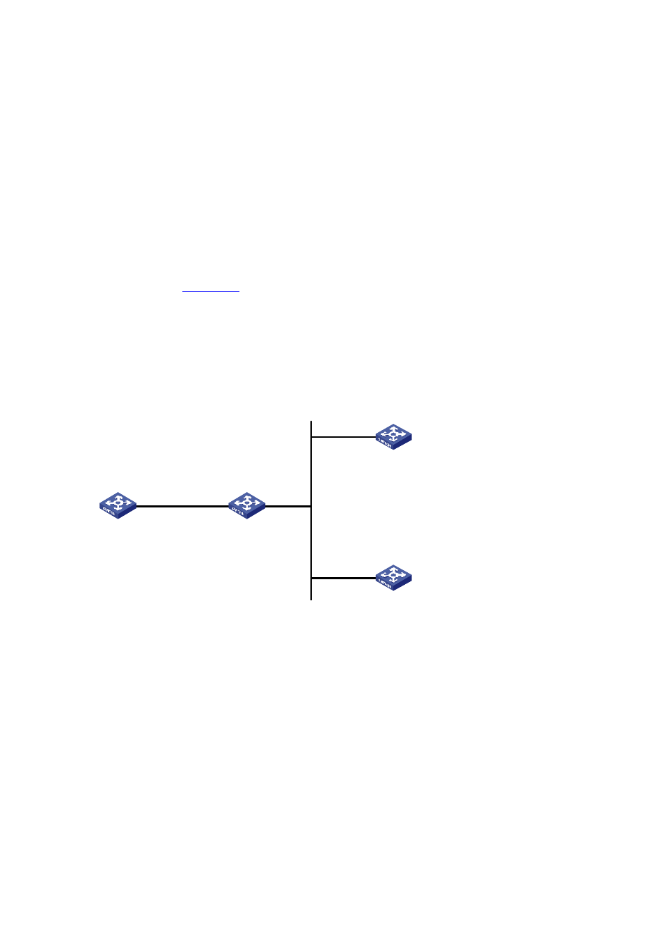
As shown in
, the local clock of Device C is set as the NTP master clock, with a stratum
level of 2. Configure Device C to work in the NTP broadcast server mode and send NTP broadcast
messages through Vlan-interface2.
z
Device A and Device D are two WX3000 series devices. Configure Device A and Device D to work
in the NTP broadcast client mode and listen to broadcast messages through their own
Vlan-interface2.
Figure 46-8
Network diagram for the NTP broadcast mode configuration
Vlan-int2
1.0.1.31/24
Vlan-int2
3.0.1.31/24
Vlan -int2
3.0.1.32/24
Device A
Device B
Device C
Device D
Configuration procedure
1) Configure Device C.
# Enter system view.
<DeviceC> system-view
# Set Device C as the broadcast server, which sends broadcast messages through Vlan-interface2.
[DeviceC] interface Vlan-interface 2
[DeviceC-Vlan-interface2] ntp-service broadcast-server
2) Configure Device A. (perform the same configuration on Device D)
# Enter system view.
<DeviceA> system-view
# Set Device A as a broadcast client.
[DeviceA] interface Vlan-interface 2
[DeviceA-Vlan-interface2] ntp-service broadcast-client