Configuration procedure – H3C Technologies H3C WX3000 Series Unified Switches User Manual
Page 216
22-47
z
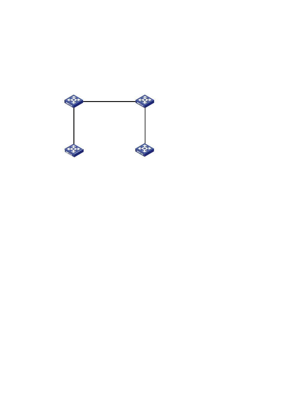
Devices of other series operate as the access devices of the user’s network, that is, Switch A and
Switch B in the network diagram.
z
Switch C and Switch D are connected to each other through the configured trunk ports of the
switches. The VLAN-VPN tunnel function is enabled in system view, thus implementing
transparent transmission between the user’s network and the operator’s network.
Figure 22-11
Network diagram for VLAN-VPN tunnel configuration
Ethernet 1/0/1
Switch A
Switch D
Switch C
Switch B
Ethernet 1/0/1
GigabitEthernet
1/0/2
GigabitEthernet
1/0/1
GigabitEthernet
1/0/2
GigabitEthernet
1/0/1
Configuration procedure
1) Configure Switch A
# Enable MSTP.
<SwitchA> system-view
[SwitchA] stp enable
# Add Ethernet 1/0/1 to VLAN 10.
[SwitchA] vlan 10
[SwitchA-Vlan10] port Ethernet1/0/1
2) Configure Switch B
# Enable MSTP.
<SwitchB> system-view
[SwitchB] stp enable
# Add Ethernet 1/0/1 to VLAN 10.
[SwitchB] vlan 10
[SwitchB-Vlan10] port Ethernet1/0/1
3) Configure Switch C
# Enable MSTP.
<SwitchC> system-view
[SwitchC] stp enable
# Enable the VLAN-VPN tunnel function.
[SwitchC] vlan-vpn tunnel
# Add GigabitEthernet 1/0/1 to VLAN 10.
[SwitchC] vlan 10
[SwitchC-Vlan10] port GigabitEthernet1/0/1
[SwitchC-Vlan10] quit
# Disable STP on GigabitEthernet 1/0/1 and then enable the VLAN VPN function on it.