Layer 2 acl configuration example, Layer 2 acl configuration example -14 – H3C Technologies H3C WX3000 Series Unified Switches User Manual
Page 343
36-14
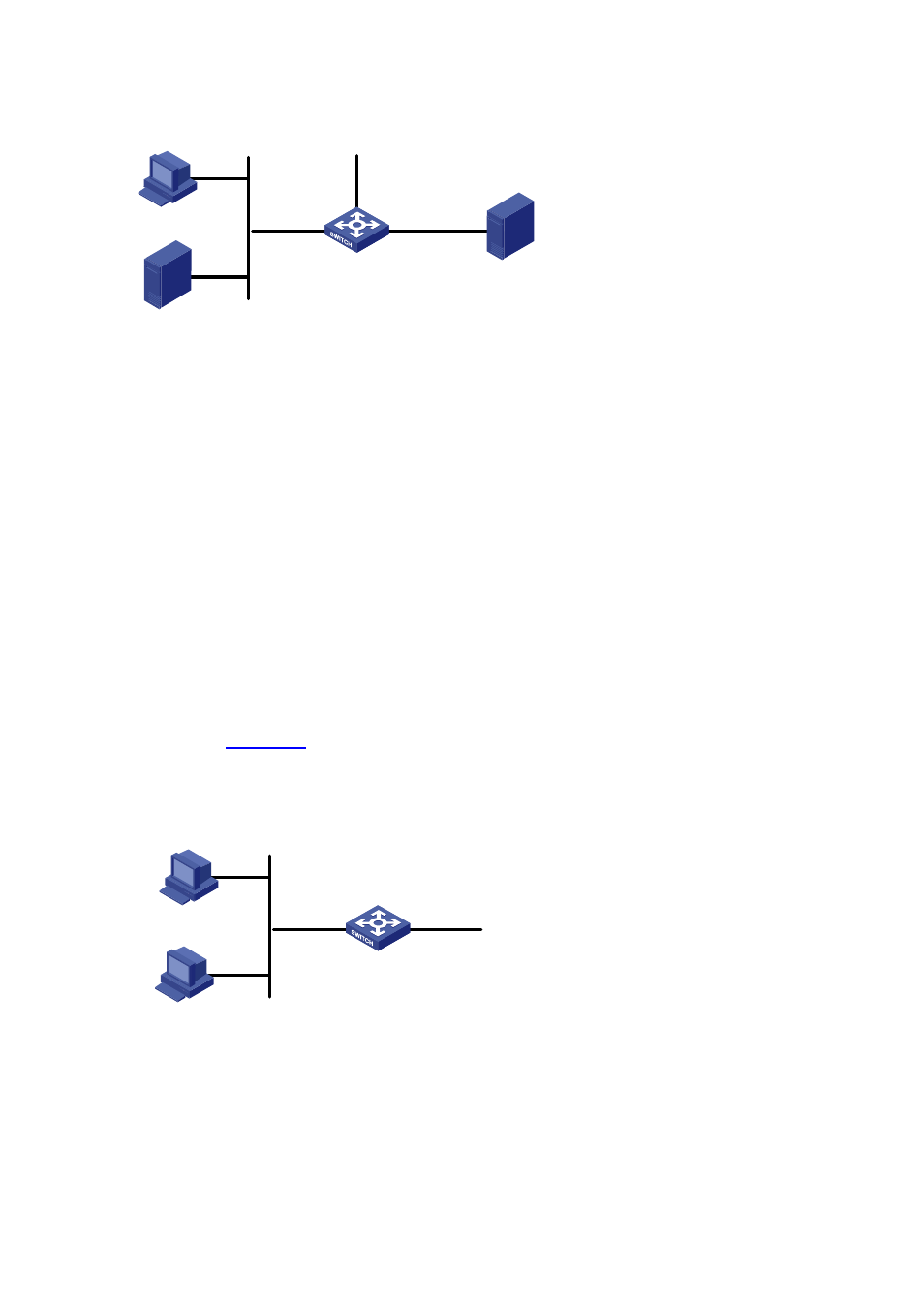
Figure 36-4
Network diagram for advanced ACL configuration
GEth1/0/1
The R&D
Department
Switch
To the router
Wage query server
192.168.1 .2
GEth1/0/2
Configuration procedure
# Define a periodic time range that is active from 8:00 to 18:00 everyday.
<device> system-view
[device] time-range test 8:00 to 18:00 working-day
# Define ACL 3000 to filter packets destined for wage query server.
[device] acl number 3000
[device-acl-adv-3000] rule 1 deny ip destination 192.168.1.2 0 time-range test
[device-acl-adv-3000] quit
# Apply ACL 3000 on GigabitEthernet 1/0/1.
[device] interface GigabitEthernet1/0/1
[device-GigabitEthernet1/0/1] packet-filter inbound ip-group 3000
Layer 2 ACL Configuration Example
Network requirements
As shown in
, PC1 and PC2 connect to Switch through GigabitEthernet 1/0/1. PC1’s MAC
address is 000f-e20f-0101. Apply an ACL to filter packets with the source MAC address of
000f-e20f-0101 and the destination MAC address of 000f-e20f-0303 from 8:00 to 18:00 everyday.
Figure 36-5
Network diagram for Layer 2 ACL
Switch
To the router
GEth1/0/1
PC1
000f-e20f-0101
PC2
Configuration procedure
# Define a periodic time range that is active from 8:00 to 18:00 everyday.
<device> system-view
[device] time-range test 8:00 to 18:00 daily