Configuration – Grass Valley NV7512 v.1.3 User Manual
Page 104
94
Rev 1.3 • 10 Oct 08
4. Configuration
Setting MADI Channels
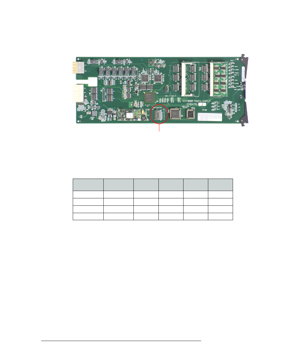
3 Locate DIP switches 1 and 2, as shown in Figure 4-8. These switches allocate channels to the
BNC connectors that receive incoming signals.
Figure 4-8. MADI Input Card Switch Location
4 Using a small, pointed object, such as a ball point pen, slide the beige switch piece to ‘ON’ or
‘OFF’ as desired. Repeat this step for each switch, setting to ‘ON’ or ‘OFF’ as needed. Input 1
refers to BNC connector ‘1’ and Input 2 refers to BNC connector ‘2’, as shown in Figure 2-10
on page 48.
The following lists each switch position and the channel allocation at each sample rate:
5 Locate DIP switches 3, 4, 5, and 6, as shown in Figure 4-8. These switches set the sample rate
for Input 1 and Input 2, and if the mode is standard or legacy.
DIP Switches
Switch 1
Switch 2
48
kHz
Input 1
48
kHz
Input 2
96
kHz
Input 1
96
kHz
Input 2
OFF
OFF
64
0
32
0
ON
OFF
56
8
28
4
OFF
ON
48
16
24
8
ON
ON
32
32
16
16