Installation, Making signal connections, Figure 2-11. analog signal connections (rear view) – Grass Valley NV7512 v.1.3 User Manual
Page 60: 1 right 2 right 4 right 3 right, 1 left 2 left 4 left 3 left, Input 2 input 4 input 8 input 6, Input 1 input 3 input 7 input 5, Mono stereo
50
Rev 1.3 • 10 Oct 08
2. Installation
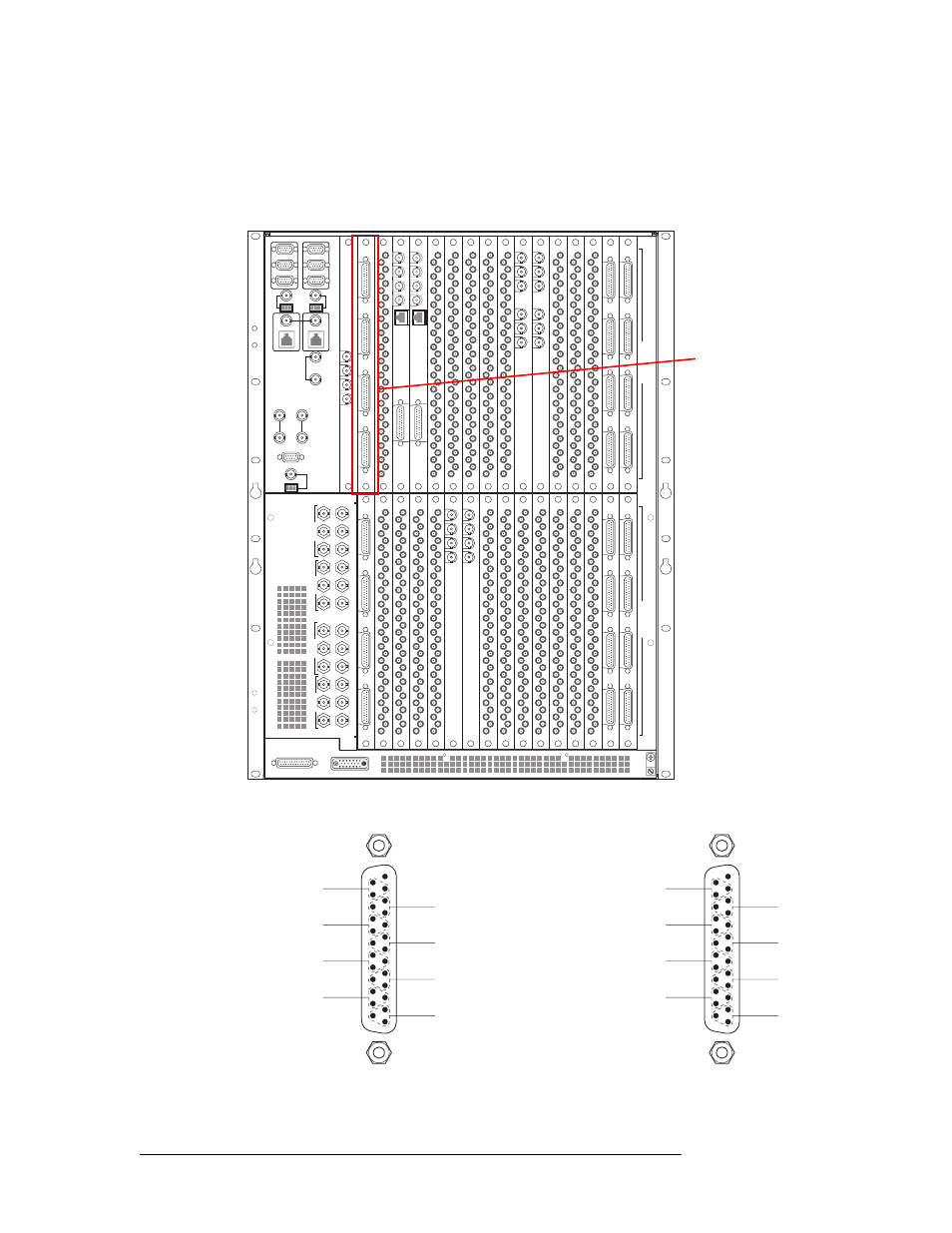
Making Signal Connections
How to make analog signal connections
1 Locate the analog input connections on the rear of the router, as shown in Figure 2-11. Inputs
are located in the lower half of the router frame. The exact location of the backplanes and corre-
sponding connectors may be different depending on your router configuration.
Figure 2-11. Analog Signal Connections (Rear View)
2 Make cable connections. The DB25 wiring is as follows:
Figure 2-12. DB25 Pin Wiring
449-480
417-448
385-416 353-384
321-352 289-320
257-288
225-256
193-224
161-192 129-160
97-128
65-96
33-64
1-32
481-512
I
N
P
U
T
S
O
U
T
P
U
T
S
22
22
22
22
22
22
22
22
22
22
22
22
22
22
22
22
22
22
22
22
QUAD MIX
OUTPUT
ANALOG
AUDIO
OUT
10/100BT
2
3
4
QUAD MIX
OUTPUT
1
QUAD MIX
OUTPUT
ANALOG
AUDIO
OUT
10/100BT
2
3
4
QUAD MIX
OUTPUT
1
OUT 1
REF 1 OUT
REF 1 IN
OUT 2
REF 2 OUT
REF 2 IN
OUT 1
REF 1 OUT
REF 1 IN
OUT 2
REF 2 OUT
REF 2 IN
MADI
INPUT
IN 1
REF 1
IN 2
REF 2
MADI
INPUT
Analog signals use DB25
connectors.
Outputs are found in the
upper half of the router
frame.
Inputs are found in the
lower half of the router
frame.
13 Unused
1 Right
2 Right
4 Right
3 Right
11
23
10
8
20
7
5
17
4
2
14
1
1 Left
2 Left
4 Left
3 Left
25
12
24
22
9
21
19
6
18
16
3
15
1
14
25
SHLD
+
SHLD
+
SHLD
+
SHLD
+
SHLD
+
SHLD
+
SHLD
+
SHLD
+
13 Unused
Input 2
Input 4
Input 8
Input 6
11
23
10
8
20
7
5
17
4
2
14
1
Input 1
Input 3
Input 7
Input 5
25
12
24
22
9
21
19
6
18
16
3
15
1
14
25
SHLD
+
SHLD
+
SHLD
+
SHLD
+
SHLD
+
SHLD
+
SHLD
+
SHLD
+
Mono
Stereo