Making signal connections, Ns, see, Ns. see – Grass Valley NV7512 v.1.3 User Manual
Page 54: Installation, Backplanes
44
Rev 1.3 • 10 Oct 08
2. Installation
Making Signal Connections
How to install the systems clock generator card
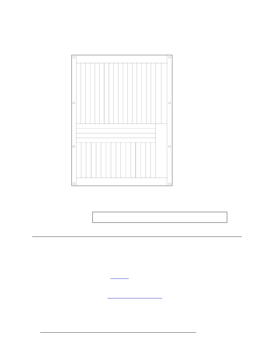
1 Locate the secondary (redundant) control card slot, as shown in Figure 2-7.
Figure 2-7. Location of Secondary Control Card (Front View)
2 Install the systems clock generator card into the slot.
3 Reinstall and close the frame front door after the card has been installed.
Making Signal Connections
In order for the NV7512 to properly route incoming and outgoing signals, the I/O connections on
the rear of the router must be connected to cables that receive and distribute the signals. The
NV7512 contains a maximum of 512 input connections and a maximum of 512 output connections.
The total number of connections depends on the type of signals being routed and the corresponding
backplane installed. (See
If connecting two or more NV7512 routers together, additional signal expansion connections must
also be connected. These connections enable the routers to send and receive signals between the
connected routers. (See
Fan
Fan
Slot A - Crosspoint (Outputs 1-128)
Slot B - Crosspoint (Outputs 129-256)
Slot C - Crosspoint (Outputs 257-384)
Slot D - Crosspoint (Outputs 385-512)
Output
s 132
Output
s 33-64
Output
s 65-96
Output
s 97-128
Output
s 129-160
Output
s 161-192
Output
s 193-224
Output
s 225-256
Output
s 257-288
Output
s 289-320
Output
s 321-352
Output
s 353-384
Output
s 385-416
Output
s 417-448
Output
s 449-480
Output
s 481-512
Control Secondary
Control Primary
Input
s 132
Input
s 33-64
Input
s 65-96
Input
s 97-128
Input
s 129-160
Input
s 161-192
Input
s 193-224
Input
s 225-256
Input
s 257-288
Input
s 289-320
Input
s 321-352
Input
s 353-384
Input
s 385-416
Input
s 417-448
Input
s 449-480
Input
s 481-512
Fan
Monitor
Note
For proper cooling, the frame must be operated with the door closed.