Madi synchronous signals, Alanced). see, Installation – Grass Valley NV7512 v.1.3 User Manual
Page 57
NV7512 Audio Router • User’s Guide
47
2. Installation
Making Signal Connections
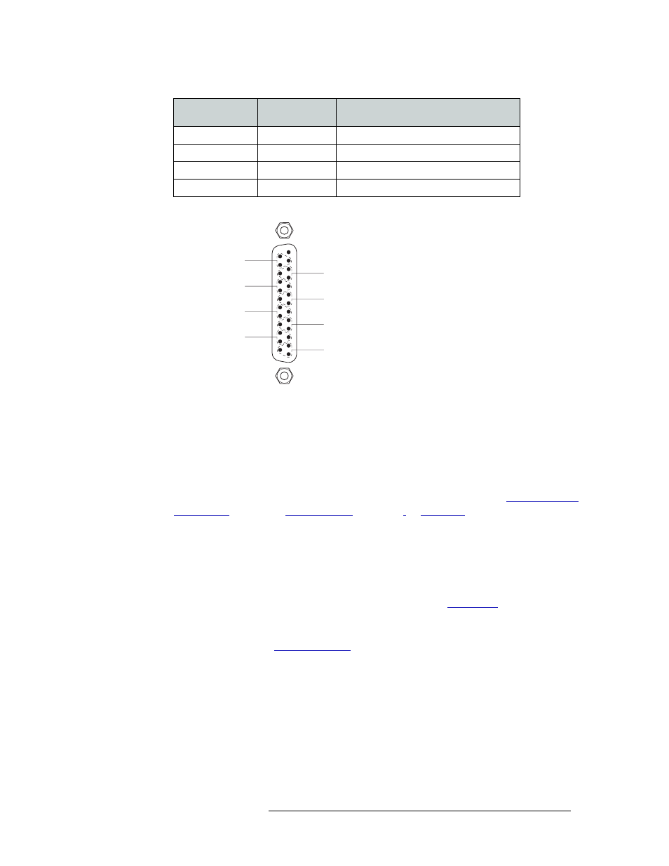
For custom wiring, wire the DB25 connector as shown in Figure 2-9. .
Figure 2-9. DB25 Pin Wiring
3 Connect the other end of the cable to the source of the signal.
4 Locate the AES output connections on the rear of the router, as shown in Figure 2-8 on page 46.
5 For each output connection, connect using the connector and cable appropriate for the type of
outgoing signal as described in Step 2.
6 Connect the other end of the cable to the signal destination.
7 Make other signal connections for MADI signals (see ), analog signals. See
,
or
8 If connecting two or more NV7512 routers together, connect the signal expansion connections.
(See Signal Expansion Connections on page 53.)
MADI Synchronous Signals
The NV7512 can manage MADI synchronous signals (unbalanced only). Signals are received and
distributed through BNC connections housed on backplanes. (See
two of the BNC connectors are used for receiving and distributing MADI signals, labeled ‘1’ and
‘2’. The remaining two BNC connectors are available to connect to a source of AES for reference.
For more information, see
Left 3
5
Green
Right 3
6
Blue
Left 4
7
Violet
Right 4
8
Gray
Signal
Wire Number
Jacket Color
(corresponds to wire number)
13 Unused
Input 2
Input 4
Input 8
Input 6
11
23
10
8
20
7
5
17
4
2
14
1
Input 1
Input 3
Input 7
Input 5
25
12
24
22
9
21
19
6
18
16
3
15
1
14
25
SHLD
+
SHLD
+
SHLD
+
SHLD
+
SHLD
+
SHLD
+
SHLD
+
SHLD
+