Installation, Xpt 3, Feet (30 – Grass Valley NV7512 v.1.3 User Manual
Page 64: Making signal connections, Frame expansion connectors
54
Rev 1.3 • 10 Oct 08
2. Installation
Making Signal Connections
• XPT 3
—
The crosspoint card installed in the center-bottom slot: ‘C’.
• XPT 4
—
The crosspoint card installed in the bottom slot: ‘D’.
Within each ‘XPT’ set, connections are labeled: ‘OUT 1’, ‘OUT 2’ and ‘OUT 3’, and ‘IN 1’, ‘IN 2’
and ‘IN 3’. Each ‘OUT’ and each ‘IN’ correspond to a segment of memory on the crosspoint card.
For more information, see
on page 29. To connect two router frames together,
you connect the ‘OUT’ connection on one router (Router 1) to the ‘IN’ connection on a second
router (Router 2). One ‘OUT’ is connected to one ‘IN’ for each crosspoint card, as shown in
Figure 2-16 on page 55.
The signal expansion connections use 75
Ω BNC connectors and Belden 1694A cable.
How to make expansion signal connections
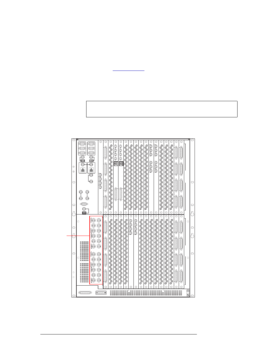
1 Locate the signal expansion connections on the rear of the router, as shown in Figure 2-15.
Figure 2-15. Signal Expansion Connections (Rear View)
Note
The routers should be placed in close proximity; the cable has a maximum length
of 100
feet (30
m).
449-480
417-448
385-416 353-384
321-352 289-320
257-288
225-256
193-224
161-192 129-160
97-128
65-96
33-64
1-32
481-512
I
N
P
U
T
S
O
U
T
P
U
T
S
22
22
22
22
22
22
22
22
22
22
22
22
22
22
22
22
22
22
22
22
QUAD MIX
OUTPUT
ANALOG
AUDIO
OUT
10/100BT
2
3
4
QUAD MIX
OUTPUT
1
QUAD MIX
OUTPUT
ANALOG
AUDIO
OUT
10/100BT
2
3
4
QUAD MIX
OUTPUT
1
OUT 1
REF 1 OUT
REF 1 IN
OUT 2
REF 2 OUT
REF 2 IN
OUT 1
REF 1 OUT
REF 1 IN
OUT 2
REF 2 OUT
REF 2 IN
MADI
INPUT
IN 1
REF 1
IN 2
REF 2
MADI
INPUT
Frame
Expansion
Connectors