Router control system connections, Introduction – Grass Valley NV7512 v.1.3 User Manual
Page 26
16
Rev 1.3 • 10 Oct 08
1. Introduction
Module Slots and Rear Connectors
Router Control System Connections
A router control system is used to manage routing configurations in the router. The router control
system sends instructions to the router control card, which in turn sends commands directing signal
switching in the router. A router control system is a separate external unit, which is connected to the
router. The NV7512 provides three types of a router control system connections: serial, Ethernet or
GSC Node Bus. The router control system determines which connection is used. For example, to
connect to the NVISION NV9000 router control system an Ethernet connection is preferred.
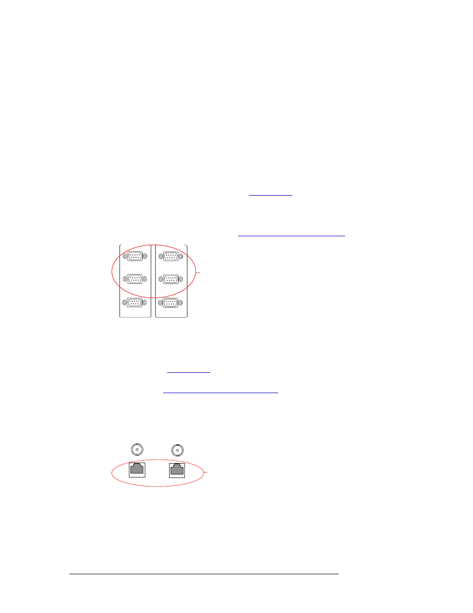
Serial Connections
The NV7512 has four serial router control system connections, as shown in Figure 1-8. The con-
nections are divided into two sets, one primary (‘PRI CTRL’) and one secondary (‘SEC CTRL’).
Primary control connects to the primary control card. Secondary control connects to the secondary
(optional for redundancy) control card. (See
on page 20.) Each set is further divided
into connections that correspond to router control systems: ‘CTRL 1’ corresponds to the primary
control system and ‘CTRL 2’ corresponds to a redundant control system. Using ‘CTRL 2’ connec-
tions, you can connect to an alternate control system (i.e., backup system) or set up dual control, if
desired. For installation instructions, see
Serial Router Control Connections
Figure 1-8. Serial Connections to Router Control System (Rear View)
Ethernet Connections
The NV7512 has two Ethernet router control system connections, labeled ‘10/100 BASET’, as
shown in Figure 1-9. Both connections are shared by the primary control card and the secondary
control card. (See
on page 20.) Because Ethernet network connections can be used to
connect to alternate control systems, there are no separate connections provided. For installation
instructions, see
Ethernet Router Control Connections
In order for the router to communicate with the router control system through an Ethernet connec-
tion, an IP address for the router needs to be set in the control card. The IP address is set using Uni-
Config. For more information, see the UniConfig User’s Guide.
Figure 1-9. Ethernet Connections to Router Control System (Rear View)
CTRL 1
CTRL 2
PRI CTRL
DIAG
Serial Connections
to Control System
CTRL 1
CTRL 2
SEC CTRL
DIAG
Ethernet
Connections
to Control
System
10 BASE 2
10/100 BASE T
10 BASE 2
10/100 BASE T
COMMON
TO
PRI & SEC