Minimum crosspoint cards required, Introduction – Grass Valley NV7512 v.1.3 User Manual
Page 35
NV7512 Audio Router • User’s Guide
25
1. Introduction
Active Cards
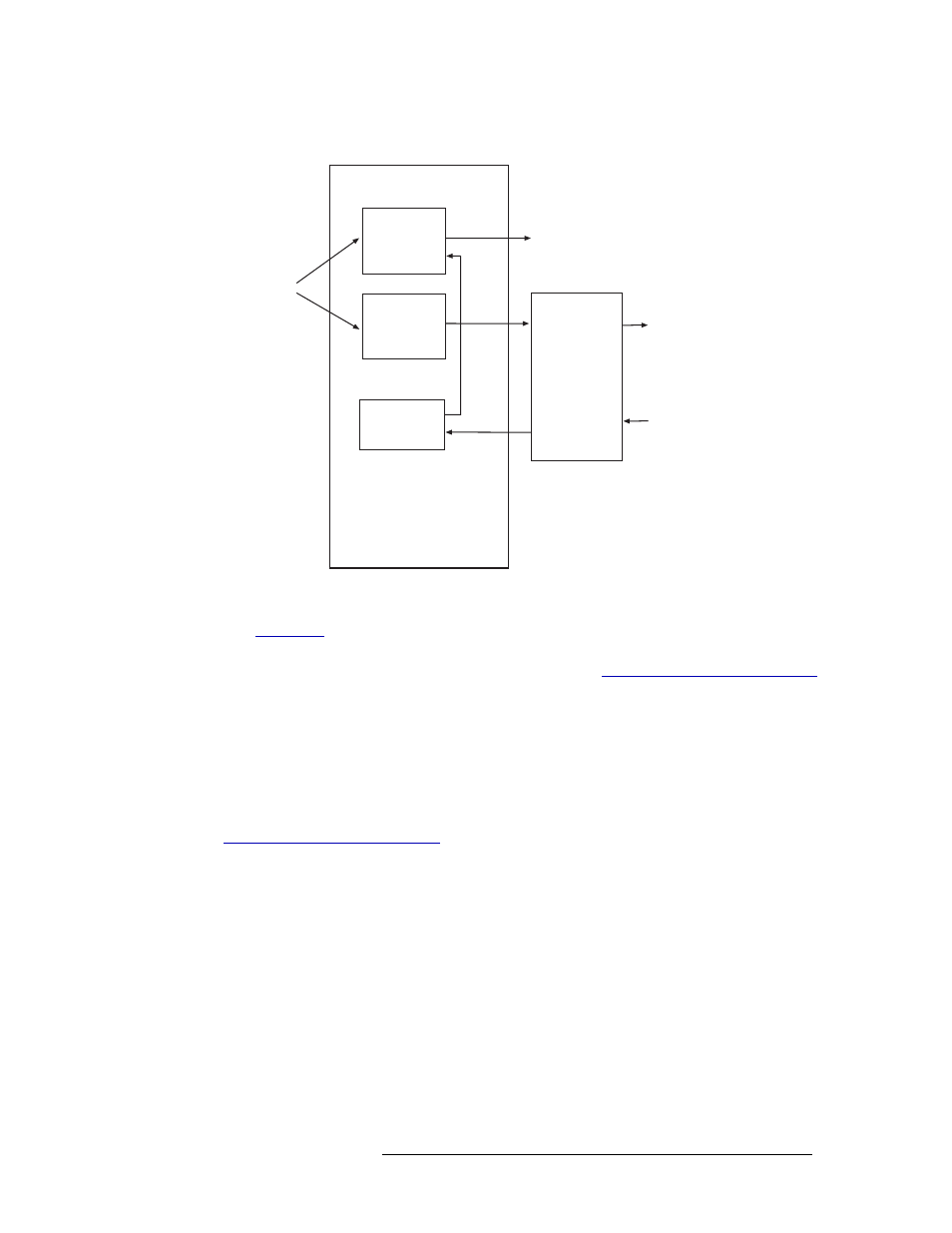
Figure 1-19 shows the flow of signals through the crosspoint card.
Figure 1-19. Crosspoint Card Block Diagram
When facing the front of the router, crosspoint cards can be installed in one of four horizontal slots.
(See
on page 9.) The slot determines which signals the crosspoint card manages. For
example, the crosspoint card installed in the top slot
—
Slot A
—
manages all inputs and outputs 1-
256. For a description of each slot and outputs managed, see
Crosspoint Card Slots and Outputs
Minimum Crosspoint Cards Required
The switching configuration being implemented determines the minimum number of crosspoint
cards required. Because each crosspoint card receives all inputs, but routes signals to only four out-
put cards, only those crosspoint cards managing outputs need to be installed. For a list of crosspoint
cards required and the slot in which a crosspoint card must be installed to route specific signals, see
Crosspoint Card Slots and Outputs
Local Inputs
via
Motherboard
TDM
Multiplexer
TDM
Demuxer
(3)
Expansion
Connectors
(up to
3 routers)
Crosspoint Card
3 copies
TDM
Crosspoint
Circuit
To connected
routers
(up to 3)
From connected
routers
(up to 3)
Local Output
Cards (4)