Making monitor connections, Installation, Figure 2-31. monitor connections (rear view) – Grass Valley NV7512 v.1.3 User Manual
Page 80: Monitor connections
70
Rev 1.3 • 10 Oct 08
2. Installation
Making Monitor Connections
Making Monitor Connections
The monitor connections on the rear of the NV7512 enable the monitoring of outgoing signals. The
monitor connections forward signals from the monitor card, which receives one signal from each
output card in the local router. By connecting monitoring equipment to the monitor connections, the
quality of signals being distributed from the router can be verified. Monitoring only supports AES
signals. For analog audio signals, only the output of the digital conversion of the analog signal is
monitored.
There are four monitor connections. Each connection can be configured to match a level set up in
the router control system. For more information on levels, see the UniConfig User’s Guide. The
monitor connections receive signals only from local output cards; no signals for monitoring pur-
poses are received from connected router frames.
Monitor connections use 75
Ω BNC connectors and coaxial cable.
How to make monitor connections
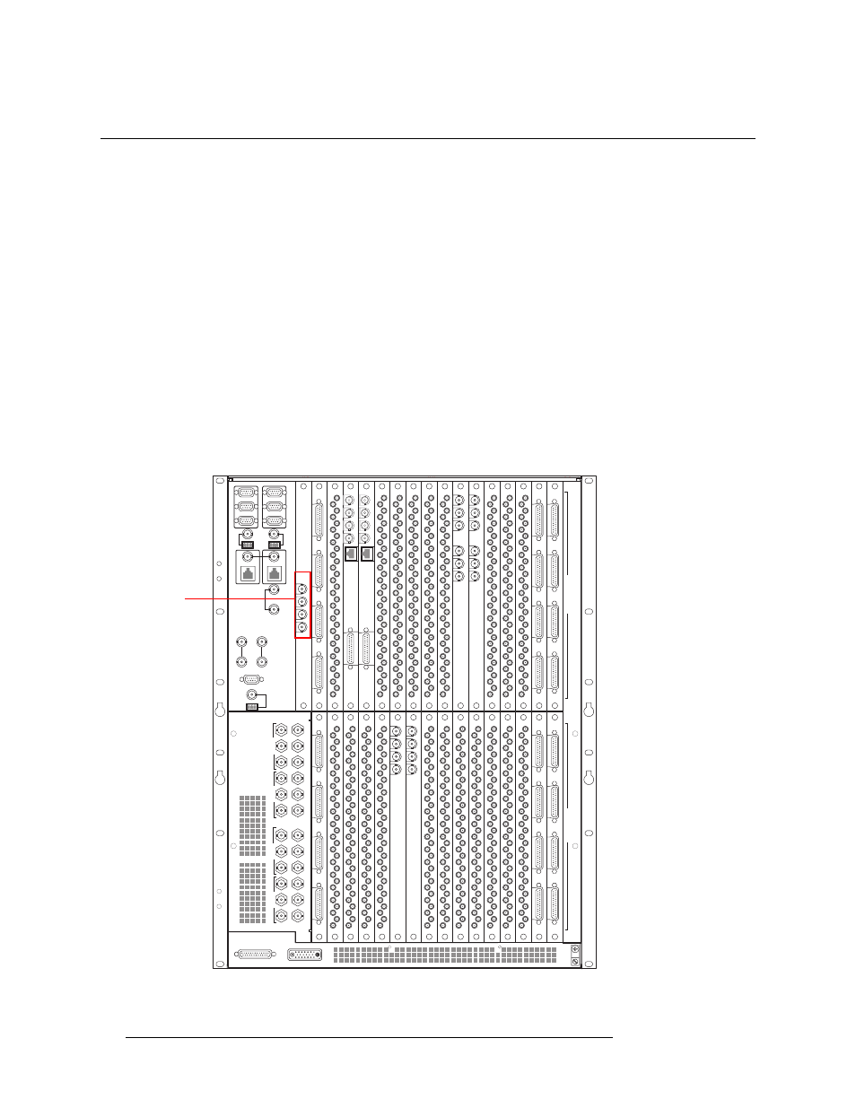
1 Locate the monitor connections on the rear of the router, as shown in Figure 2-31. Monitor con-
nections are labeled, ‘1’, ‘2’, ‘3’ and ‘4’.
Figure 2-31. Monitor Connections (Rear View)
449-480
417-448
385-416 353-384
321-352 289-320
257-288
225-256
193-224
161-192 129-160
97-128
65-96
33-64
1-32
481-512
I
N
P
U
T
S
O
U
T
P
U
T
S
22
22
22
22
22
22
22
22
22
22
22
22
22
22
22
22
22
22
22
22
QUAD MIX
OUTPUT
ANALOG
AUDIO
OUT
10/100BT
2
3
4
QUAD MIX
OUTPUT
1
QUAD MIX
OUTPUT
ANALOG
AUDIO
OUT
10/100BT
2
3
4
QUAD MIX
OUTPUT
1
OUT 1
REF 1 OUT
REF 1 IN
OUT 2
REF 2 OUT
REF 2 IN
OUT 1
REF 1 OUT
REF 1 IN
OUT 2
REF 2 OUT
REF 2 IN
MADI
INPUT
IN 1
REF 1
IN 2
REF 2
MADI
INPUT
Monitor
Connections