Installation, Making power connections, 22 fan – Grass Valley NV7512 v.1.3 User Manual
Page 49
NV7512 Audio Router • User’s Guide
39
2. Installation
Making Power Connections
5 Facing the rear of the first router (Router 1), connect the other end of the power supply cable
to ‘POWER INPUT’, as shown in Figure 2-3 on page 37.
6 Facing the rear of the NV6257, using the remaining power supply cable (WC0085), connect
one end of the cable to ‘Output Power 1’, as shown in Figure 2-2 on page 36.
7 Facing the rear of the second router (Router 2), connect the other end of the power supply
cable to ‘POWER INPUT’, as shown in Figure 2-3 on page 37.
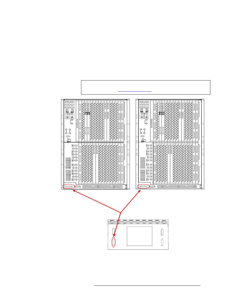
8 Facing the rear of the NV6257, connect the “Y” cable to ‘Power Supply Monitors’, as shown in
Figure 2-5.
Figure 2-5. “Y” Cable Connecting Two Routers to a Single NV6257
9 Facing the rear of the first router (Router 1), connect one of the two remaining monitor “Y”
cable connectors to ‘POWER SUPPLY MONITORS’, as shown in Figure 2-5.
Important
For Steps 8, 9 and 10 be sure to use the connector wired for the connection you
are connecting to (see
449-480
417-448
385-416 353-384
321-352 289-320
257-288
225-256
193-224
161-192 129-160
97-128
65-96
33-64
1-32
481-512
449-480
417-448
385-416 353-384
321-352 289-320
257-288
225-256
193-224
161-192 129-160
97-128
65-96
33-64
1-32
481-512
I
N
P
U
T
S
O
U
T
P
U
T
S
I
N
P
U
T
S
O
U
T
P
U
T
S
22
22
22
22
22
22
22
22
22
22
22
22
22
22
22
22
22
22
22
22
22
22
22
22
22
22
22
22
22
22
22
22
22
22
22
22
22
22
22
22
FAN
Output
Power 1
Output
Power 2
Power
Supply
Monitors
Alarms
A Y cable has three DB25
connectors, one on each end
of the serial cables, creating
a Y.
You connect one end to the
Power Supply Monitor
connection on each router
and another end to the
NV6257 Power Supply
Monitors connection.
QUAD MIX
OUTPUT
ANALOG
AUDIO
OUT
10/100BT
2
3
4
QUAD MIX
OUTPUT
1
QUAD MIX
OUTPUT
ANALOG
AUDIO
OUT
10/100BT
2
3
4
QUAD MIX
OUTPUT
1
QUAD MIX
OUTPUT
ANALOG
AUDIO
OUT
10/100BT
2
3
4
QUAD MIX
OUTPUT
1
QUAD MIX
OUTPUT
ANALOG
AUDIO
OUT
10/100BT
2
3
4
QUAD MIX
OUTPUT
1
OUT 1
REF 1 OUT
REF 1 IN
OUT 2
REF 2 OUT
REF 2 IN
OUT 1
REF 1 OUT
REF 1 IN
OUT 2
REF 2 OUT
REF 2 IN
OUT 1
REF 1 OUT
REF 1 IN
OUT 2
REF 2 OUT
REF 2 IN
OUT 1
REF 1 OUT
REF 1 IN
OUT 2
REF 2 OUT
REF 2 IN
MADI
INPUT
IN 1
REF 1
IN 2
REF 2
MADI
INPUT
MADI
INPUT
IN 1
REF 1
IN 2
REF 2
MADI
INPUT