Diagnostic connections, Introduction – Grass Valley NV7512 v.1.3 User Manual
Page 27
NV7512 Audio Router • User’s Guide
17
1. Introduction
Module Slots and Rear Connectors
GSC Node Bus Connections
Some third-party router control systems require a GSC Node Bus connection. The NV7512 has one
GSC Node Bus connection, labeled ‘NODE BUS’, as shown in Figure 1-10. The connection is
shared by both the primary control card and the secondary control card. (See
page 20.) To use the GSC Node Bus connection, an optional module must be installed on each con-
trol card being used. For details, contact NVISION. For installation instructions, see
Bus Router Control Connections
Figure 1-10. GSC Node Bus Connections to Router Control System (Rear View)
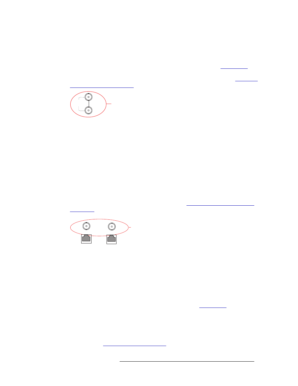
Router Control System Expansion Connections
In order to manage multiple connected NV7512 routers, the router control system expansion con-
nections need to be connected between the routers. Control system expansion connections are
located on the rear of the router, labeled ‘10 BASE 2’, as shown in Figure 1-11.
When making router control system connections, only one router is directly connected to the router
control system. This router acts as the primary router. When connecting two or more routers, each
router’s control system expansion connection is connected to the next router in line, ending with the
primary router. For example, if connecting four routers, Router 4 is connected to Router 3, which is
connected to Router 2, and Router 2 is connected to Router 1. Router 1 is the primary router and
connected directly to the router control system. This enables the router control system to communi-
cate with all connected routers through the primary router’s control system connection. For instruc-
tions on making control system expansion connections, see
Router Control System Expansion
Figure 1-11. Expansion Control System Connections (Rear View)
Diagnostic Connections
The diagnostic connections enable the NV7512 to communicate with the UniConfig application.
UniConfig runs on external hardware (e.g., PC) separate from the router and is used to perform sys-
tem setup tasks, and configure and monitor the router. For more information on UniConfig, see the
UniConfig User’s Guide.
There are two types of diagnostic connections: temporary and permanent. A temporary diagnostic
serial connection is located on the front of each control card. (See
on page 20.) Per-
manent diagnostic connections are located on the rear of the router, labeled ‘DIAG’, as shown in
Figure 1-12 on page 18. NVISION recommends using the temporary diagnostic connection when
configuring the router because the port has fixed communications parameters. The permanent diag-
nostic connections are used for upgrading firmware or control card protocols when there is no
Ethernet connection to the router. For instructions on making temporary or permanent diagnostic
connections, see
LOOP
THRU
GSC Node Bus
Connection
to Control System
NODE
BUS
10 BASE 2
10/100 BASE T
10 BASE 2
10/100 BASE T
COMMON
TO
PRI & SEC
Expansion
Connections for
Control System