Gain and mute detection, Setting ana, Log gain, mute detection and operating levels – Grass Valley NV7512 v.1.3 User Manual
Page 97: Configuration, When the gain switch is set to on, a +18, Input generates a +24
NV7512 Audio Router • User’s Guide
87
4. Configuration
Setting Analog Gain, Mute Detection and Operating Levels
Setting Analog Gain, Mute Detection and Operating Levels
The analog input card includes several DIP switch sets and jumpers that determine the gain, mute
detection and operating level of incoming signals. Additionally, the operating level of outgoing sig-
nals can be set on the analog output card. For more information on each card functions, see
on page 23 for analog input cards and
on page 28 for analog output cards.
Gain and Mute Detection
The analog input card features four, 8-position DIP switch sets that allow the gain of each channel
to be increased by 6
dB
. These switches are labeled SW1 through SW4. With the switch in the OFF
position, gain is normalized at 0
dBu
. With the switch in the ON position, the gain is increased by
6
dB
. There are 32 switches, one for each channel. A channel is defined as a left or right input
respectively.
These switches only affect input gain. The router output continues to operates with an effective
FSD of +24
dBu
. When the Gain switch is set to ON, a +18
dBu
input generates a +24
dBu
output.
This card also contains a Mute Detect enable jumper. When the analog audio input level drops to –
78
dB
or lower for more than 0.25 per second, the output sample values are replaced with digital
silence. This jumper affects all inputs on the card, turning the mute function on or off for all inputs
globally.
How to set analog gain and mute detection
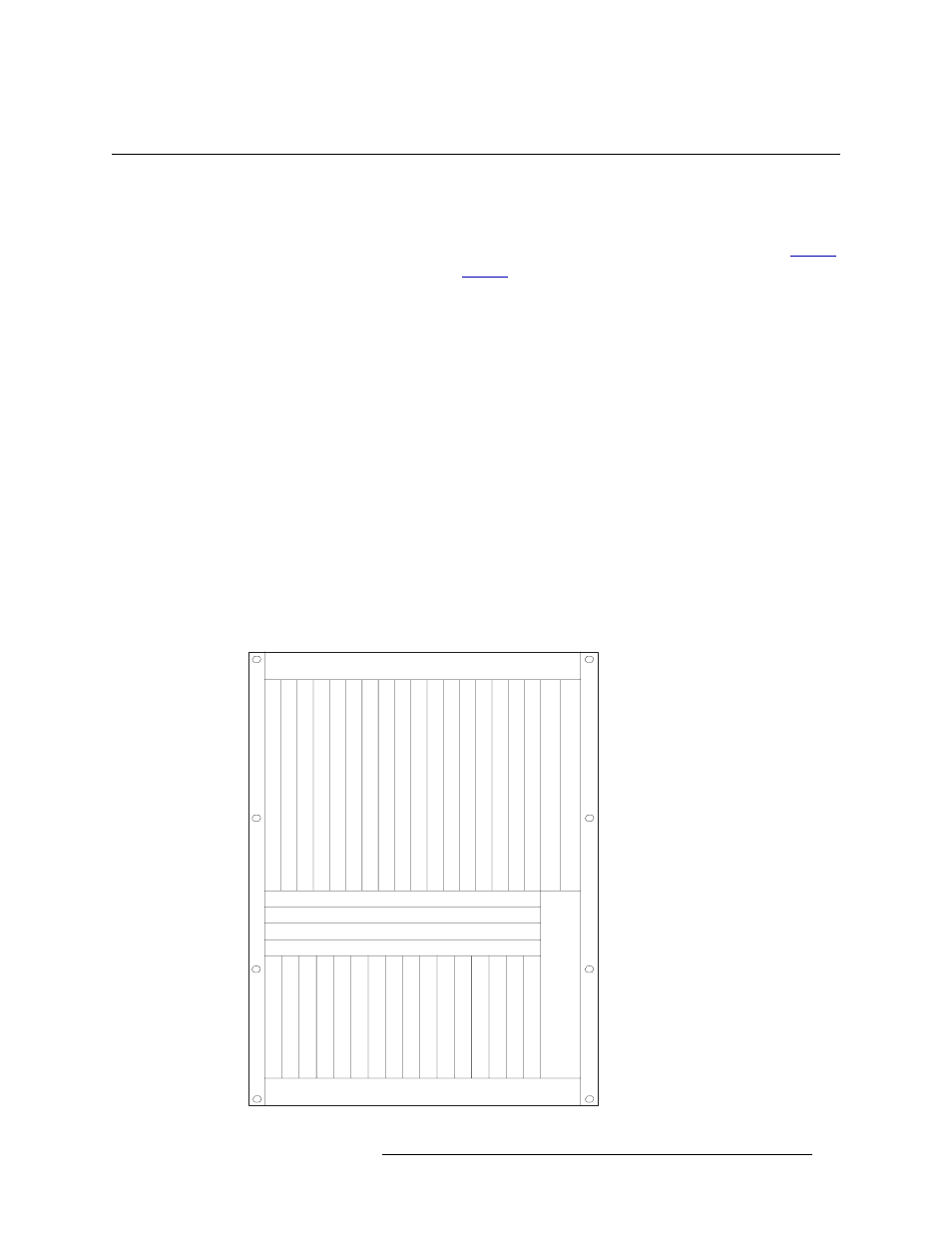
1 Locate the analog input cards, as shown in Figure 4-5.
Fan
Fan
Slot A - Crosspoint (Outputs 1-128)
Slot B - Crosspoint (Outputs 129-256)
Slot C - Crosspoint (Outputs 257-384)
Slot D - Crosspoint (Outputs 385-512)
Output
s 132
Output
s 33-64
Output
s 65-96
Output
s 97-128
Output
s 129-160
Output
s 161-192
Output
s 193-224
Output
s 225-256
Output
s 257-288
Output
s 289-320
Output
s 321-352
Output
s 353-384
Output
s 385-416
Output
s 417-448
Output
s 449-480
Output
s 481-512
Control Secondary
Control Primary
Input
s 132
Input
s 33-64
Input
s 65-96
Input
s 97-128
Input
s 129-160
Input
s 161-192
Input
s 193-224
Input
s 225-256
Input
s 257-288
Input
s 289-320
Input
s 321-352
Input
s 353-384
Input
s 385-416
Input
s 417-448
Input
s 449-480
Input
s 481-512
Fan
Monitor