Creating a “y” cable, Installation – Grass Valley NV7512 v.1.3 User Manual
Page 50
40
Rev 1.3 • 10 Oct 08
2. Installation
Making Power Connections
10 Facing the rear of the second router (Router 2), connect the remaining monitor “Y” cable con-
nector to ‘POWER SUPPLY MONITORS’, as shown in Figure 2-5 on page 39.
11 Facing the rear of the NV6257, connect a power cord from an AC power source (90–130/180–
230
VAC, 50/60
Hz) into power connections PS 1 through PS 8. Connect one power cord for
each PS6000 power supply module installed (see Step 12).
12 Install the PS6000 power supply modules as follows:
a Facing the front of the NV6257, install the primary PS6000 power supply modules in slots
PS 1, PS 3, PS 5 and PS 7, as shown in Figure 2-4 on page 38.
b (Optional) Facing the front of the NV6257, install redundant PS6000 power supply modules
in slots PS 2, PS4, PS6 and PS 8, as shown in Figure 2-3 on page 37.
13 Facing the rear of each router (Router 1, Router 2), connect each ground lug to ground using a
copper wire from 14 to 6 AWG. The ground lug is located in the lower, right-hand corner.
Creating a “Y” Cable
A “Y” cable is needed to connect two router frames to a single NV6257. A “Y” cable is a cable that
has one connector at one end, but then splits and has two separate connectors on the other end.
NVISION does not supply this cable at this time.
To create a “Y” cable you need:
• Three male DB25 connectors
• Two standard PC printer cables (remove any pre-attached connectors)
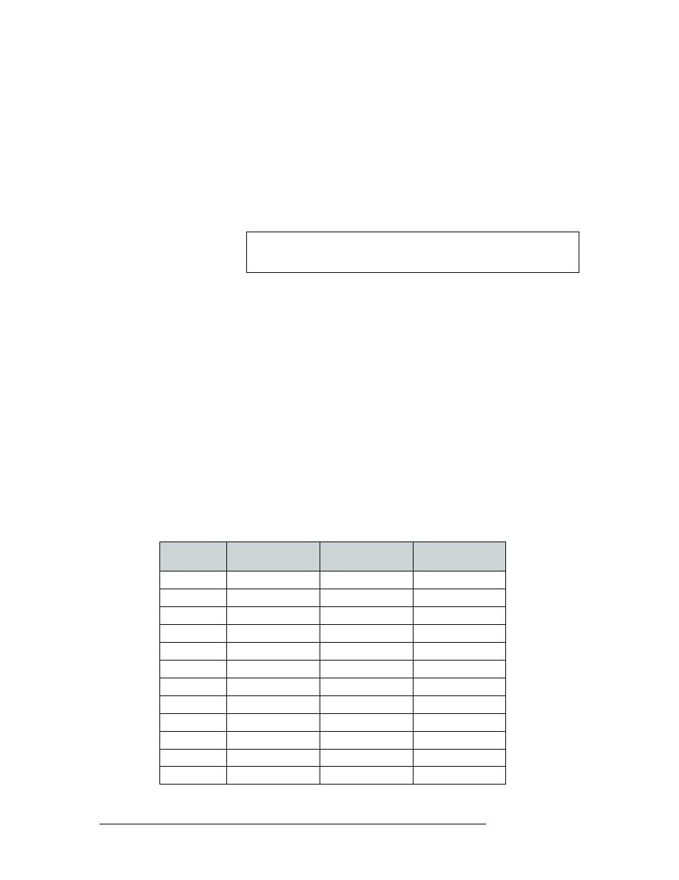
Wire the pins on the DB25 connectors as listed in the following table. To ensure that the correct
connector is inserted in the corresponding connection, it is recommended that each connector be
labeled according to its destination connection.
Note
The NV6257 fans are powered by slot PS 1 or PS 2. A PS6000 must be
installed in one of these slots.
DB25 Pin
NV6257 Connector
Router 1
Connector
Router 2
Connector
20
PS_TACH
PS_TACH
PS_TACH
21
PS_ALARM1
PS_ALARM1
PS_ALARM5
19
PS_ALARM2
PS_ALARM2
PS_ALARM6
18
PS_ALARM3
PS_ALARM3
PS_ALARM7
17
PS_ALARM4
PS_ALARM4
PS_ALARM8
16
PS_ALARM5
NC
NC
15
PS_ALARM6
NC
NC
23
PS_ALARM7
NC
NC
22
PS_ALARM8
NC
NC
8
TEMP1
TEMP1
TEMP5
6
TEMP2
TEMP2
TEMP6
5
TEMP3
TEMP3
TEMP7