Installing a systems clock generator (optional), Installing a systems clock generator, Optional) – Grass Valley NV7512 v.1.3 User Manual
Page 53: Installation
NV7512 Audio Router • User’s Guide
43
2. Installation
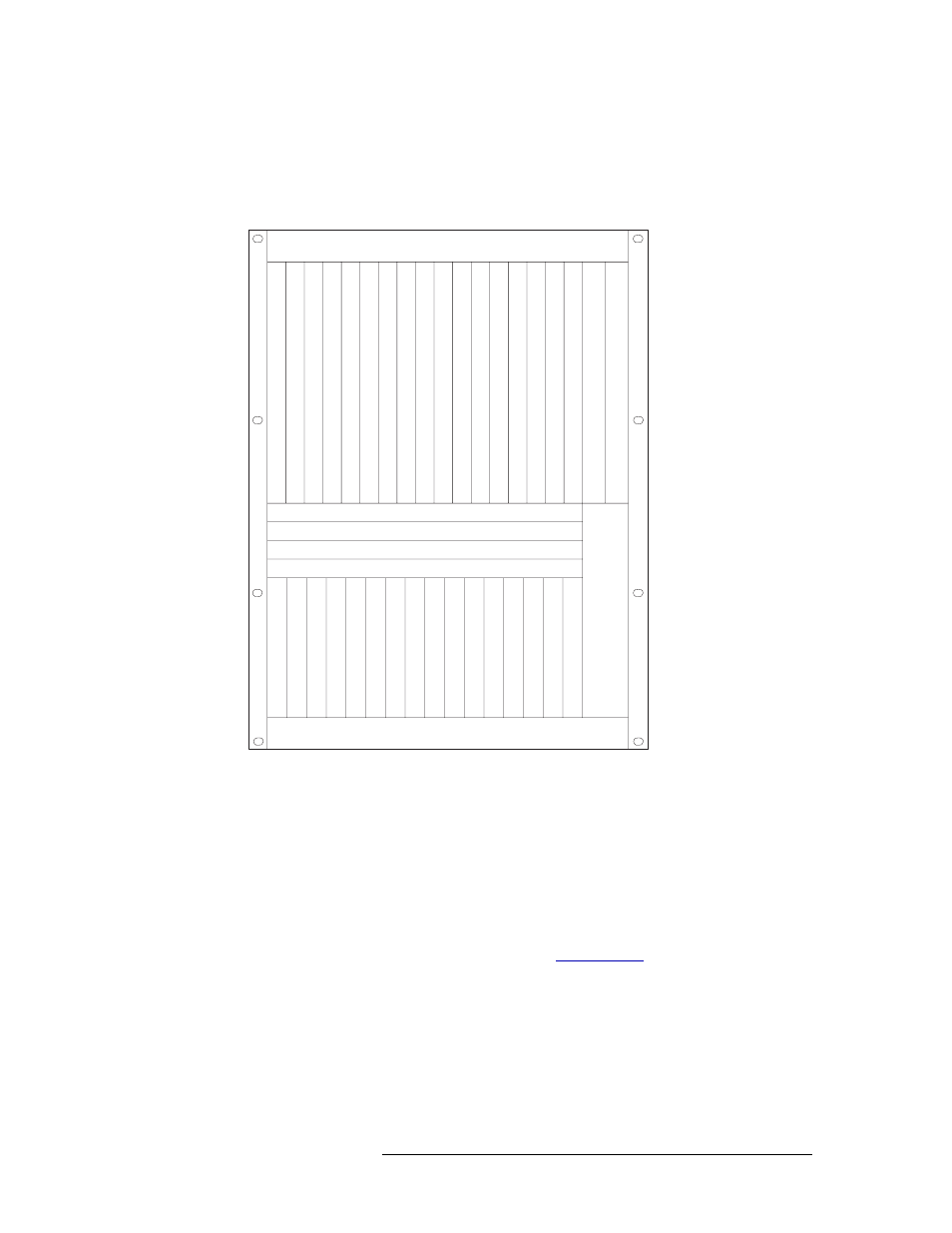
Installing Active Cards
• Insert crosspoint cards in the horizontal center slots. Locking levers are located at the right
and left edges of each card.
• Insert the optional monitor card in the upper bay slot between output card slot 16 and the
secondary control card slot. Locking levers are located at the top and bottom of the card.
Figure 2-6. Active Module Locations (Front View)
3 Press each lever downward so that the lever is tucked into the channel at the edge of the shelf on
the top and bottom. When the door is closed, pressure from the door ensures that the card is
fully seated with the motherboard.
4 Reinstall and close the frame front door after all cards have been installed. The door must be
closed for the router cooling system to work properly.
Installing a Systems Clock Generator (Optional)
The system clock is located on the control card. (See
on page 20.) This clock is crit-
ical and used by all input cards and output cards; if the clock fails, the router cannot route signals.
As a preventive measure, a secondary (optional for redundancy) control card can be installed to act
as a backup should the primary control card fail. If you do not want to install two control cards, an
optional systems clock generator card (EM0414) can be installed in place of the secondary control
card. The systems clock generator card ensures that in the event of a primary control card failure
the system continues to receive clock information. However, the systems clock generator card only
provides clock information and cannot take over control card tasks.
Fan
Fan
Slot A - Crosspoint (Outputs 1-128)
Slot B - Crosspoint (Outputs 129-256)
Slot C - Crosspoint (Outputs 257-384)
Slot D - Crosspoint (Outputs 385-512)
Output
s 132
Output
s 33-64
Output
s 65-96
Output
s 97-128
Output
s 129-160
Output
s 161-192
Output
s 193-224
Output
s 225-256
Output
s 257-288
Output
s 289-320
Output
s 321-352
Output
s 353-384
Output
s 385-416
Output
s 417-448
Output
s 449-480
Output
s 481-512
Control Secondary
Control Primary
Input
s 132
Input
s 33-64
Input
s 65-96
Input
s 97-128
Input
s 129-160
Input
s 161-192
Input
s 193-224
Input
s 225-256
Input
s 257-288
Input
s 289-320
Input
s 321-352
Input
s 353-384
Input
s 385-416
Input
s 417-448
Input
s 449-480
Input
s 481-512
Fan
Monitor