5 close the router door, Configuration – Grass Valley NV7512 v.1.3 User Manual
Page 96
86
Rev 1.3 • 10 Oct 08
4. Configuration
Control Card Jumper Settings
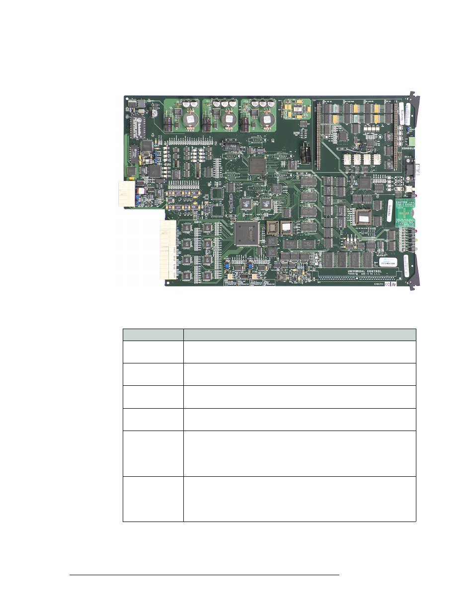
3 On the card, locate each jumper by its label number, placing jumper sleeves as needed, as
shown in Figure 4-2. Jumpers are colored blue.
Figure 4-2. Control Card
The following lists each jumper label number, function, and correct setting. Any jumpers not
listed are unused and should be left in the factory position:
4 When all jumpers are set, gently slide the control card back into place in the router frame.
5 Close the router door.
Jumper Label
Settings
J1 SBUS/10B2
Sets rear connectors labeled 10Base2 to be used for Ethernet.
Default set to lower 10Base2 position.
J2 SBUS/10B2
Sets rear connectors labeled 10Base2 to be used for Ethernet.
Default set to lower 10Base2 position.
J4 SMS7/SBUS
Sets rear Node Bus connectors to be used for third-party router control systems.
Default set to upper SMS7000 position.
J6 SMS7/SBUS
Sets rear Node Bus connectors to be used third-party router control systems.
Default set to upper SMS7000 position.
J13 AES REF2
Sets the rear AES REF 2 input impedance to 110
Ω
, 75
Ω
, or HiZ (high
impedance).
Upper position selects 110
Ω
for use with Phoenix rear connectors, the middle
position selects 75
Ω
for use with BNC rear connectors, or the lower position
selects HiZ if this input is the last connection in an equipment chain.
J16 AES REF1
Sets the rear AES REF 1 input impedance to 110
Ω
, 75
Ω
, or HiZ (high
impedance).
Upper position selects 110
Ω
for use with Phoenix rear connectors, the middle
position selects 75
Ω
for use with BNC rear connectors, or the lower position
selects HiZ if this input is the last connection in an equipment chain.