Madi (unbalanced), Introduction – Grass Valley NV7512 v.1.3 User Manual
Page 32
22
Rev 1.3 • 10 Oct 08
1. Introduction
Active Cards
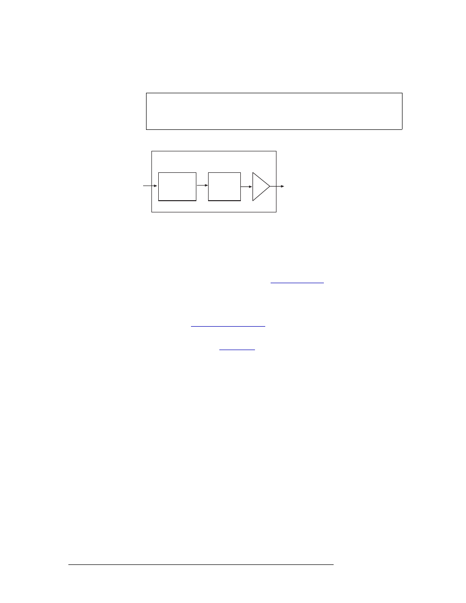
The receiver forwards the signal to a buffer, which in turns sends the signal to the motherboard and
onward to all crosspoint cards.
Figure 1-16 shows the signal flow for an AES synchronous input card.
Figure 1-16. AES Synchronous Input Card Block Diagram
MADI (Unbalanced)
The MADI input card (EM0476) supports incoming MADI unbalanced signals received through
local BNC coaxial connectors. MADI audio signals are grouped into 32-bit packets for each audio
channel with one MADI frame composed of up to 64 continuous channels. MADI signals require a
reference in accordance with AES11 standards. (See
Using DIP switches on the input card, channels can be allocated between the two BNC connectors.
In addition, the sample rate of the MADI signal, whether standard or legacy format, can be set and
if channel status data remains untouched or forced to match common professional channel status.
For more information, see
Asynchronous MADI signals are supported if two Sample Rate Converter (SM0478) sub-module
are installed on the input card. (See
on page 20.) MADI streams containing asynchro-
nous audio data use the same input card, output card, and backplane as MADI synchronous signals.
The MADI input card can receive up to 64 audio channels. Each MADI signal is transformer cou-
pled to remove “noise” and forwarded to a receiver. The receiver extracts clock and data informa-
tion, removing any unnecessary synchronization information. The signal is then forwarded to a
MADI processing module, which performs two functions: If a Sample Rate Converter sub-module
has been installed, the processing module formats the signal for rate conversion by the sub-module.
The Sample Rate Converter sub-module recombines any asynchronous signal data as a digital sig-
nal with a sample rate of 48kHz or 96kHz for internal routing and forwards the signal back to the
processing module.
If a Sample Rate Converter sub-module is not installed, the processing modules recombines signal
data to create a signal with a sample rate of 48kHz or 96kHz for internal routing. From the process-
ing module, all signals are forwarded to a buffer. The buffer feeds the signal to the motherboard and
onward to all crosspoint cards.
Note
Near-synchronous operation may cause minor disturbances in the audio signal.
These effects are usually masked by the program audio, depending on the sample
rate offset or magnitude and timing of the disturbance.
Local Input
Connectors
(up to 32)
Transformer
Coupled
All
Crosspoints
Input Card
Receiver