Installation – Grass Valley NV7512 v.1.3 User Manual
Page 72
62
Rev 1.3 • 10 Oct 08
2. Installation
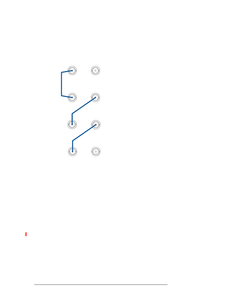
Making Router Control System Connections
2 On Router 1 (the router directly connected to the control system), connect to the left
‘10 BASE 2’ connection using a 50
Ω BNC connector and coaxial cable, as shown in Figure 2-
23.
Figure 2-23. Control System Expansion Connections Between Routers
3 Connect the other end of the cable to the left ‘10 BASE 2’ connection on Router 2, using a
50
Ω BNC connector, as shown in Figure 2-23.
4 On Router 2, connect to the right ‘10 BASE 2’ connection using a 50
Ω BNC connector and
coaxial cable, as shown in Figure 2-23 on page 62.
5 Connect the other end of the cable to the left ‘10 BASE 2’ connection on Router 3, using a
50
Ω BNC connector, as shown in Figure 2-23 on page 62.
6 On Router 3, connect to the right ‘10 BASE 2’ connections using aa 50
Ω BNC connector and
coaxial cable, as shown in Figure 2-23 on page 62.
7 Connect the other end of the cable to the left ‘10 BASE 2’ connection on Router 4, using a
50
Ω BNC connector, as shown in Figure 2-23 on page 62.
8 On Router 4, connect to the right ‘10 BASE 2’ connections using a 50
Ω BNC terminator
(NVISION part 1211598).
10 BASE 2
10 BASE 2
Router 1
10 BASE 2
10 BASE 2
Router 2
10 BASE 2
Router 3
10 BASE 2
10 BASE 2
10 BASE 2
Router 4
Terminate unused looping
connectors using a 50W
terminator.
50 W terminattion required on
unused connector on starting router.
50 W terminattion required on
unused connector on ending router.