Installation – Grass Valley NV7512 v.1.3 User Manual
Page 61
NV7512 Audio Router • User’s Guide
51
2. Installation
Making Signal Connections
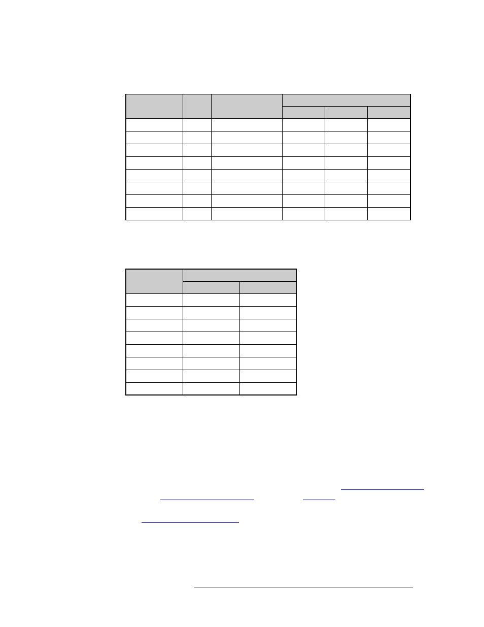
An optional pre-made DB25 male to pigtail breakout cable is available from NVISION
(NV5000-Cable1). The balanced wiring details for this cable are as follows:
For single-ended wiring, connect the signal or “hot” wire from the source to the “+” input and
connect the common or “shield” wire from the source to the “–” input. Bridge the ground pin
to the “–” pin:
3 Connect the other end of the cable to the source of the signal.
4 Locate the analog output connections on the rear of the router, as shown in Figure 2-11 on
page 50.
5 For each output, connect using a DB25 connector and cable, wiring the connectors as described
in Step 2.
6 Connect the other end of the cable to the signal destination.
7 Make other signal connections for AES signals, MADI signals. See
on page 52, as needed.
8 If connecting two or more NV7512 routers together, connect the signal expansion connections.
Channel
Pair
Jacket Color
DB25 Connector Pin Number
Red (+)
Black (–)
GND
1 - Left
1
BROWN
24
12
25
1 - Right
2
RED
10
23
11
2 - Left
3
ORANGE
21
9
22
2 - Right
4
YELLOW
7
20
8
3 - Left
5
GREEN
18
6
19
3 - Right
6
BLUE
4
17
5
4 - Left
7
VIOLET
15
3
16
4 - Right
8
GRAY
1
14
2
Note: Pin 13 is not used.
Channel
DB25 Connector Pin Number
Signal
Common
1 - Left
24
12, 25
1 - Right
10
11, 23
2 - Left
21
9, 22
2 - Right
7
8, 20
3 - Left
18
6, 19
3 - Right
4
5, 17
4 - Left
15
3, 16
4 - Right
1
2, 14
Note: Pin 13 is not used.