Yaskawa E7 Drive User Manual User Manual
Page 107
Programming 5 - 33
For applications employing a Drive that is oversized for the motor, E2-01 may be set as low as 10% of the Drive output current
rating. The AMP value in E2-01, however, must always be greater than the “No Load Current” value in parameter E2-03 or an
OPE02 error will be displayed.
E2-03 No Load Current
Setting Range:
Model Dependent (see Appendix B)
Factory Default: Model Dependent
Set E2-03 to the motor no-load current at rated voltage and rated frequency. Consult the motor manufacturer for the proper
value if the no load current is not stated on the motor nameplate.
F6 Com OPT Setup (applies only to the LonWorks option)
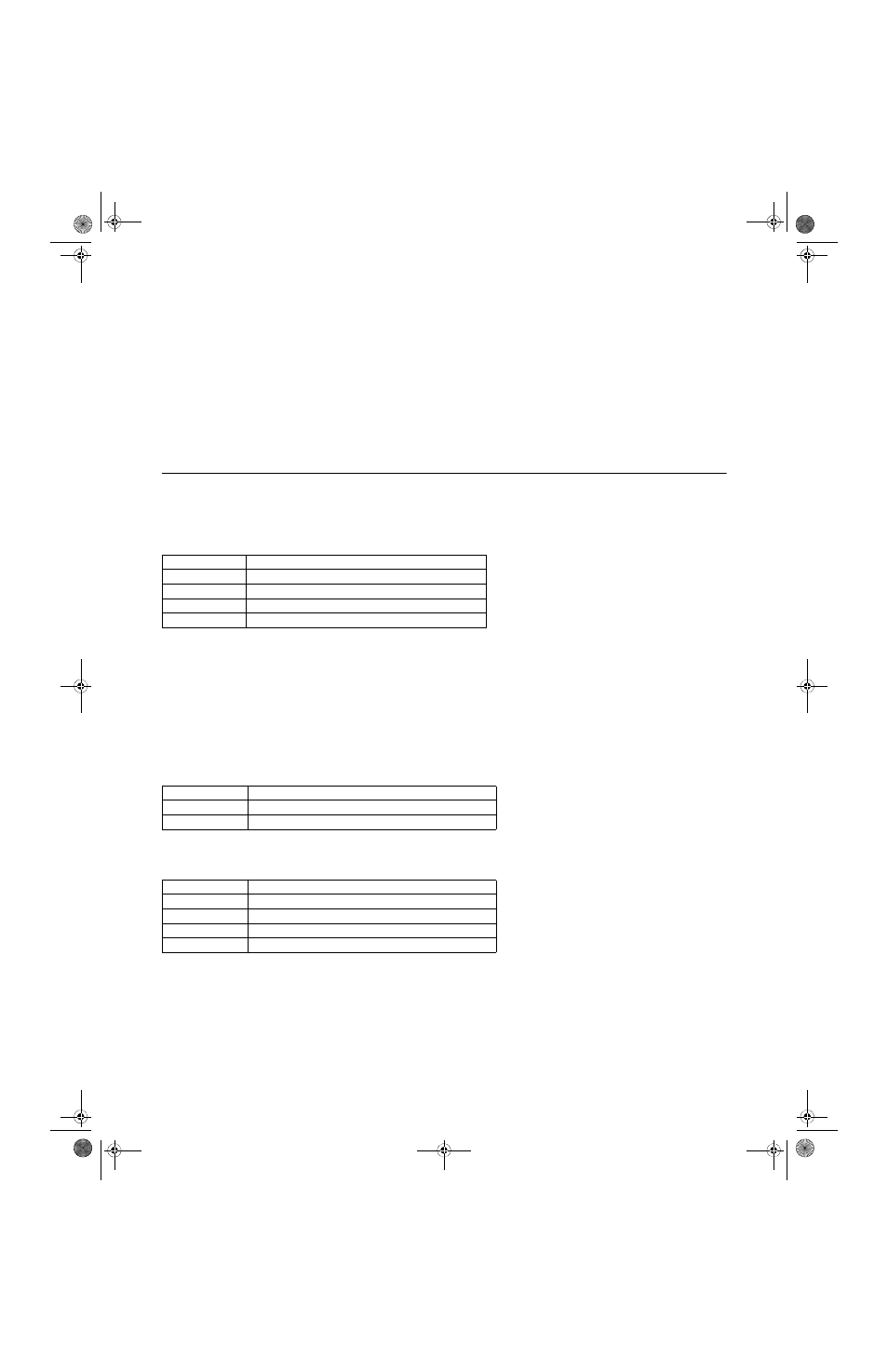
F6-01 Operation Selection After Communication Error
If a serial communication option board is attached to the Drive at the 2CN connector, the Drive will automatically monitor the
card for any type of communication errors. F6-01 is applicable no matter whether a run command or speed command is com-
ing via the option board, digital operator, or terminal input. The setting of F6-01 determines whether the communication error
is seen as a fault or an alarm. If F6-01= “3: Alarm Only”, then the fault output is not energized upon a communication error.
All other settings of F6-01 cause the fault output to energize. The setting of F6-01 does not apply to any of the embedded com-
munication protocols used at the RS-485/422 terminals on the removable terminal board. (See parameters H5-0X).
F6-02 Option PCB External Fault Detection Selection
F6-03 Option PCB External Fault Stopping Method
If an external fault is received from the L
ON
W
ORKS®
or other communication option card, the settings of F6-02 and F6-03 will
determine the Drive operation in reaction to the fault signal. Parameter F6-02 will determine if the external fault is always
recognized (F6-02= “0: Always Detected”) or only recognized when the Run command is active (F6-02= “1: Detected only
during operation”).
Setting
Description
0
Ramp to Stop
1
Coast to Stop (factory default)
2
Fast-Stop
3
Alarm Only
Setting
Description
0
Always Detected (factory default)
1
Detected only during operation
Setting
Description
0
Ramp to Stop
1
Coast to Stop (factory default)
2
Fast-Stop
3
Alarm Only
TM_E7_01_07182008.book Page 33 Wednesday, July 23, 2008 2:35 PM