Terminal block configuration, Terminal block configuration -2, Electrical installation 2 - 2 – Yaskawa E7 Drive User Manual User Manual
Page 30: The wiring terminals are shown in fig 2.1, Fig 2.1 drive terminal configuration, Ground terminal
Advertising
Electrical Installation 2 - 2
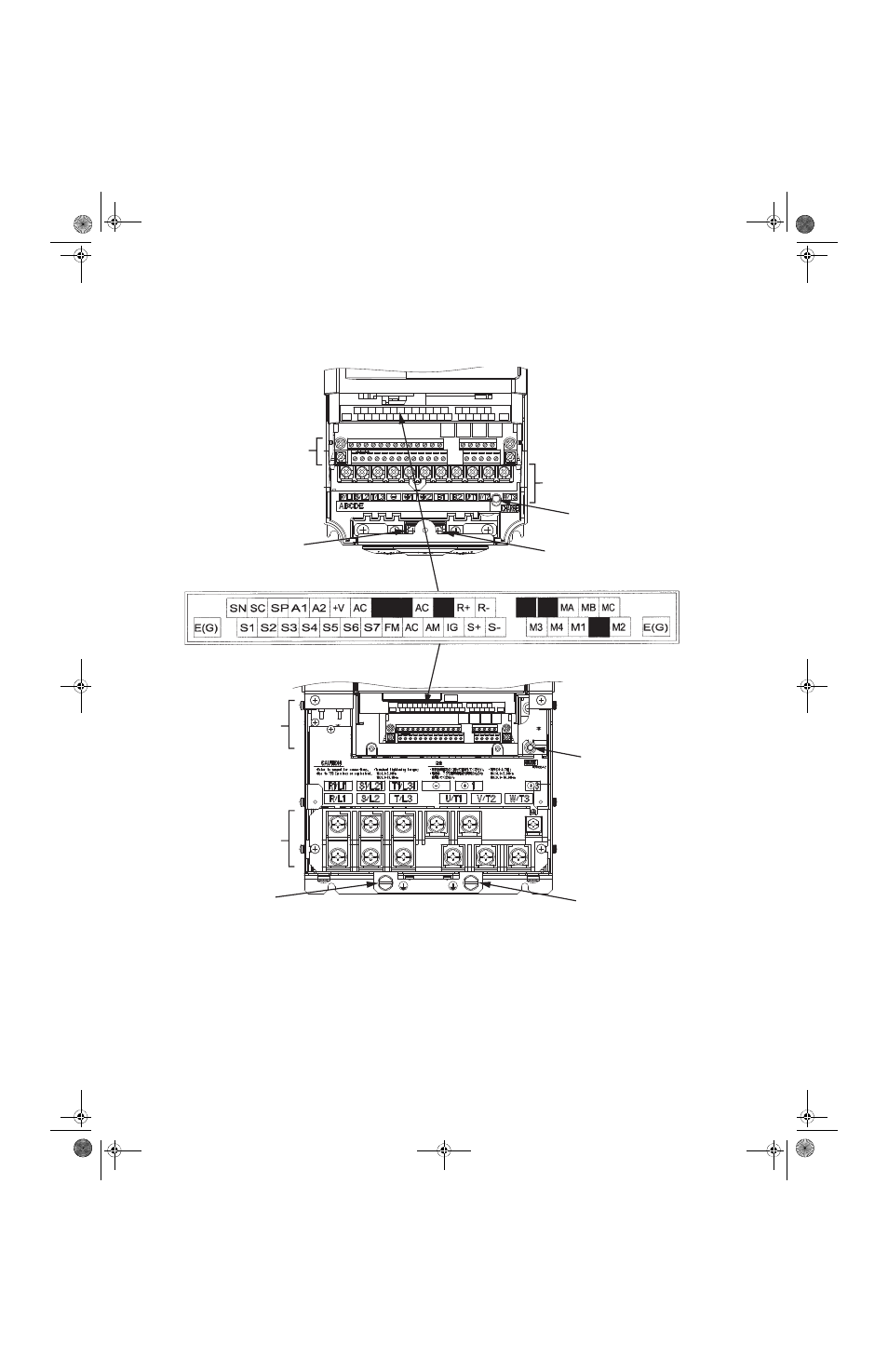
Terminal Block Configuration
The wiring terminals are shown in Fig 2.1.
Fig 2.1 Drive Terminal Configuration
Models CIMR-_ _ _ 2022 (30 HP, 208V)/
4030 (40 HP, 480V) and larger
AC
MP
AM
S6
-V
IG
R-
M5
FM
R+
RP
S1
S4
SP
S7
M4
+V
S3
SC
S+
A2
M2
SN
M6
AC
A1
E(G)
E(G)
MC
MB
S5
M1
AC
MA
M3
S2
S-
AC
MP
AM
S6
-V
IG
R-
M5
FM
R+
RP
S1
S4
SP
S7
M4
+V
S3
SC
S+
A2
M2
SN
M6
AC
A1
E(G)
E(G)
MC
MB
S5
M1
AC
MA
M3
S2
S-
Models CIMR-_ _ _ 2018 (25 HP, 208V)/
4018 (30 HP, 480V) and smaller
Ground terminal
Ground terminal
Ground terminal
Ground terminal
Charge indicator
Main circuit terminals
Main circuit terminals
Control circuit terminals
Control circuit terminals
Charge indicator
TM_E7_01_07182008.book Page 2 Wednesday, July 23, 2008 2:35 PM
Advertising
This manual is related to the following products: