H3 analog inputs -34, H3 analog inputs, Programming 5 - 34 – Yaskawa E7 Drive User Manual User Manual
Page 108
Programming 5 - 34
Once the fault is recognized, parameter F6-03 will determine the operation of the Drive. If parameter F6-03 is set to anything
other then “3”, the Drive will fault and a stopping sequence is begun. If F6-03= “3: Alarm Only”, then the external fault is
treated like an alarm. Operation will continue and an EF0 fault will flash on the digital operator.
F6-05 Current Scaling via Communication Option PCB
A communication option card can read the Drive’s DPRAM to access the current monitor. The format of the current reading in
the DPRAM will be determined by parameter F6-05.
F6-05= “0: A Display” Current is a decimal number corresponding to actual Amperes
F6-05= “1: 100%/8192 (Drive Rated Current)”
Current reading is a number where
8192 = 100% of Drive rated output current
H3 Analog Inputs
H3-02 Terminal A1 Gain Setting
Setting Range:
0.0 to 1000.0%
Factory Default: 100.0%
H3-03 Terminal A1 Bias Setting
Setting Range:
-100.0% to +100.0%
Factory Default: 0.0%
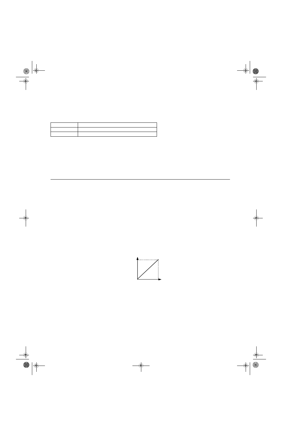
In order to have the Drive properly interpret an analog input, it may be necessary to apply a gain and/or a bias to the signal.
The analog inputs have a resolution of 11 bits (1024 steps). Using the factory default settings for the analog input’s gain and
bias, the 0-10Vdc or 4-20mA signal at the analog input will yield a 0-100% speed command span.
Note:
11 bits if 0 to 10 Vdc (A1, A2, A3) and 10 bits if 4-20mA (A2 only).
Fig 5.23 Output Frequency as Commanded Via Analog Input
If a different span of analog input signal is desirable, it will be necessary to adjust the gain, the bias, or both to allow the analog
input level to generate the desired frequency command. Adjustment of the gain setting will change the speed command that is
equivalent to the maximum analog input (10Vdc or 20mA). If, for instance, the gain is increased to 200%, then 10Vdc or
20mA will be equivalent to a 200% speed command and 5 VAC or 12mA will be equivalent to a 100% Speed Command.
Since the Drive output is limited by the maximum frequency parameter (E1-04), 0-5Vdc or 4-12mA will now be equivalent to
0-100% speed command span.
Setting
Description
0
A Display (factory default)
1
100%/8192 (Drive Rated Current)
20mA
4mA
0V
10V
Gain = 100%
Bias = 0%
Ou
tp
ut
Fr
eq
ue
nc
y
Analog Input Level
Signal
TM_E7_01_07182008.book Page 34 Wednesday, July 23, 2008 2:35 PM