Installation and start-up, Physical installation – Yaskawa DSD 406 User Manual
Page 17
Advertising
2
Installation and Start-Up
13
Physical Installation
3/21/96
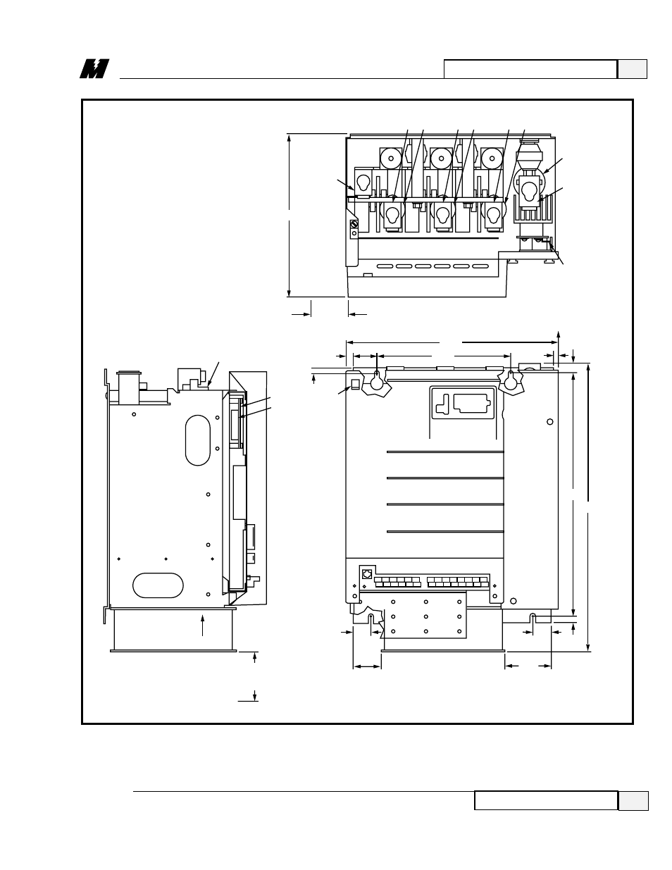
Figure 3.1. Dimensions and Mounting Holes
DSD 412
150-200 Hp Versions
4.00 MINIMUM
CLEARANCE
REQUIRED
AIR FLOW
1.94
2.13
FAN
FAN
3.50
1.69
23.49
19.50
0.50
A4
TB3
17.09
10.75
0.505
0.83
12.50 MIN.
WIRE BEND
ALLOWANCE
1.94
0.58
2.38 MIN.
DOOR SWING
0.438
12.93
GND
ARM (–)
GND
UNPLUG TB3
FROM HEADER
WHILE
INSTALLING
WIRES.
LA-100
TB1
A1
J2
8
7
6
5
4
3
2
1
(TERMINAL BLOCK QTY PER DRIVE SPECIFICATION)
L1 F1
L2 F2
L3 F3
F4
ARM(+)
MOTOR
FIELD
CONNECTIONS
GND
Advertising
This manual is related to the following products: