Yaskawa DSD 406 User Manual
Page 22
2
Installation and Start-Up
18
Electrical Hook-Up
3/21/96
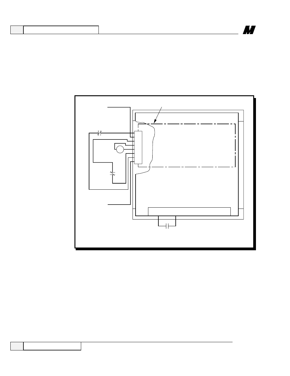
Figure 6. Connections to TB3 and TB1 DSD Power Cube –
Ratings up to 206 Amps
❏ On units rated at 206A or less, connect the motor field lead F1 (+) to
A3TB4(F1+), and motor field lead F2 (-) to Field Control Module (F2–).
(Refer to Figure 5.)
❏ On units rated at 206A Iarm or less, connect armature voltage sensing lead
(A1) to Armature Interface PCB(A2) TB5-2(+), and connect armature
voltage sensing lead (A2) to Armature Interface PCB TB5-1(–).
(Refer to Figure 5.)
115 VAC LO
(NEUTRAL)
MOTOR
THERMOSTAT
MOTOR
LOOP
CONTACTOR
K1
COAST
STOP
115 VAC HI
(HOT)
K1 AUX
TBI
48
43
42
84
DSD DRIVE CONTROL PCB (A1)
FRONT VIEW OF SWING OUT DOOR
TB3
8
7
6
5
4
3
2
1
LA-1
1
DSD POWER SUPPLY PCB (A4)
7
❏ On units rated 206A Iarm or less, connect the motor armature A1 lead
through contactor N.O. contact to fuse F4 (in a DSD 412) or terminal E5 (in
a DSD 406). (Refer to Figure 5.)
❏ On units rated at 206A Iarm or less, connect the motor armature A2 lead
through armature contactor N.O. contact to terminal ‘NEG’. (Refer to
Figure 5.)