Yaskawa DSD 406 User Manual
Page 23
❏ Connect 115 VAC control power to the DSD Power Supply PCB(A4), TB3-
1 (Hot) and (A4)TB3-7 (Neutral). This source must be rated at 250 VA or
greater. (Refer to Figure 6.)
❏ Connect the armature (motor loop) contactor coil to DSD Power Supply
PCB, (A4)TB3-4 and (A4)TB3-5. (Refer to Figure 6.)
❏ An auxiliary 10ma, 24VDC, low power, normally open (N.O.) contact from
the armature (motor loop) contactor must be connected to DSD Drive
Control PCB, (A1)TB1-48 and (A1)TB1-7, for the drive to operate.
(Refer to Figure 6.)
❏ The Coast Stop push button (maintained, 10ma, 24VDC, low power), MUST
BE CONNECTED to the DSD Power Supply PCB, (A4)TB3-3 and (A4)
TB3-6. (Refer to Figure 6.)
❏ Connect a grounding wire from the ground pole to the ground terminal
provided. The ground terminal is marked GND, and is located near the
power input and output terminals.
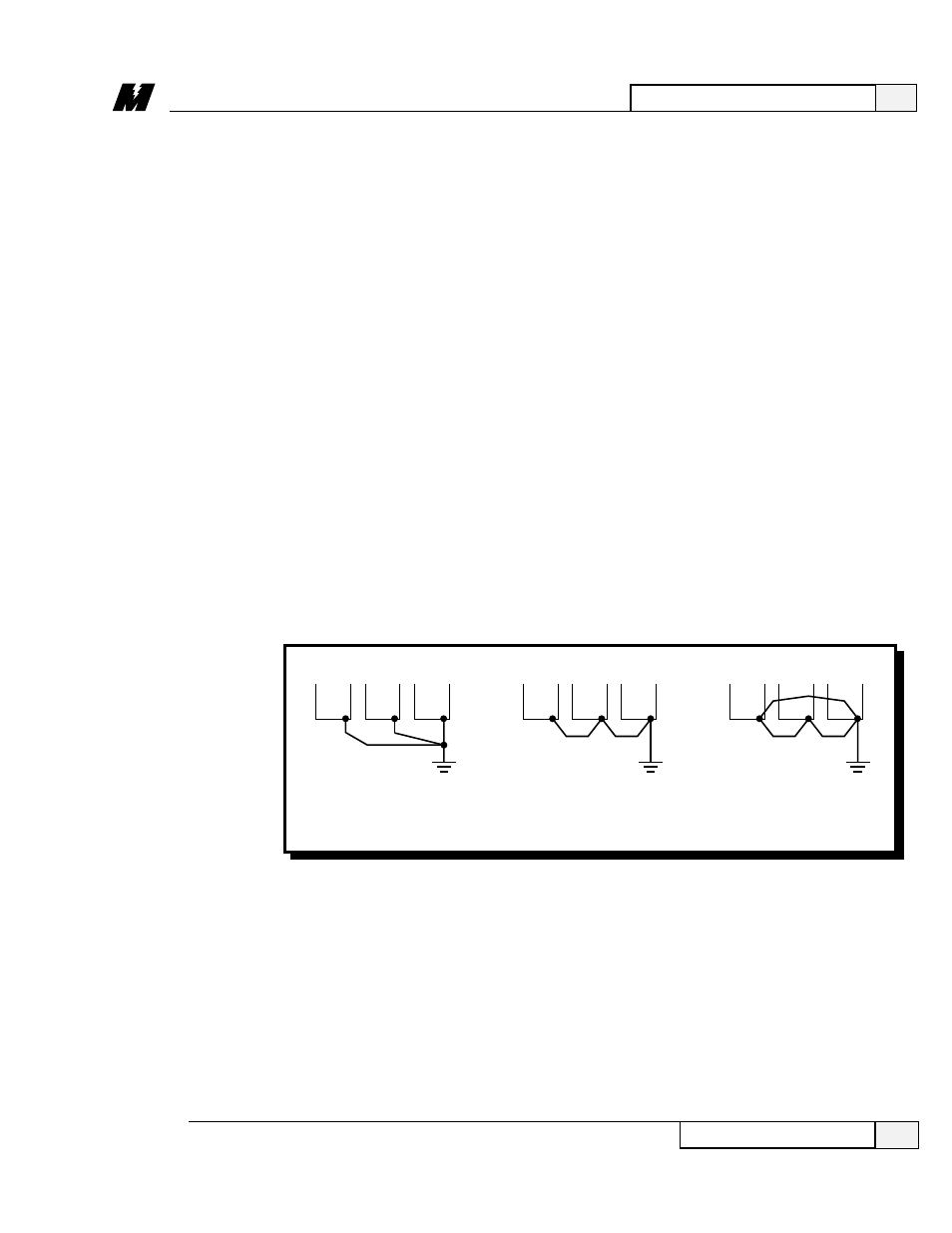
❏ Where several units are used side by side, all units should be grounded
directly to the ground pole. However, it is permissible to connect all the
ground terminals in series and ground only one unit to the ground pole (refer
to Figure 7). DO NOT FORM A LOOP WITH THE GROUND WIRES.
2
Installation and Start-Up
19
Electrical Hook-Up
3/21/96
❏ If dynamic braking resistors (DBR) are to be used, connect across motor
armature in series with loop contactor N.C. contact. (See Figure 5.)
Figure 7. Grounding of Multiple Units
CORRECT
CORRECT
NOT
ACCEPTABLE
GROUND
POLE
GROUND
POLE
GROUND
POLE
LA-10