Installation and start-up, Electrical hook-up – Yaskawa DSD 406 User Manual
Page 21
2
Installation and Start-Up
17
Electrical Hook-Up
3/21/96
For a NEMA 1 or open panel mounted drive, refer to the equipment
Interconnection Diagram for detailed wiring information.
If only a power cube was ordered, the following connections need to be made
(refer to Figures 5 and 6 for location of terminating points on drives rated up to
330 Amps):
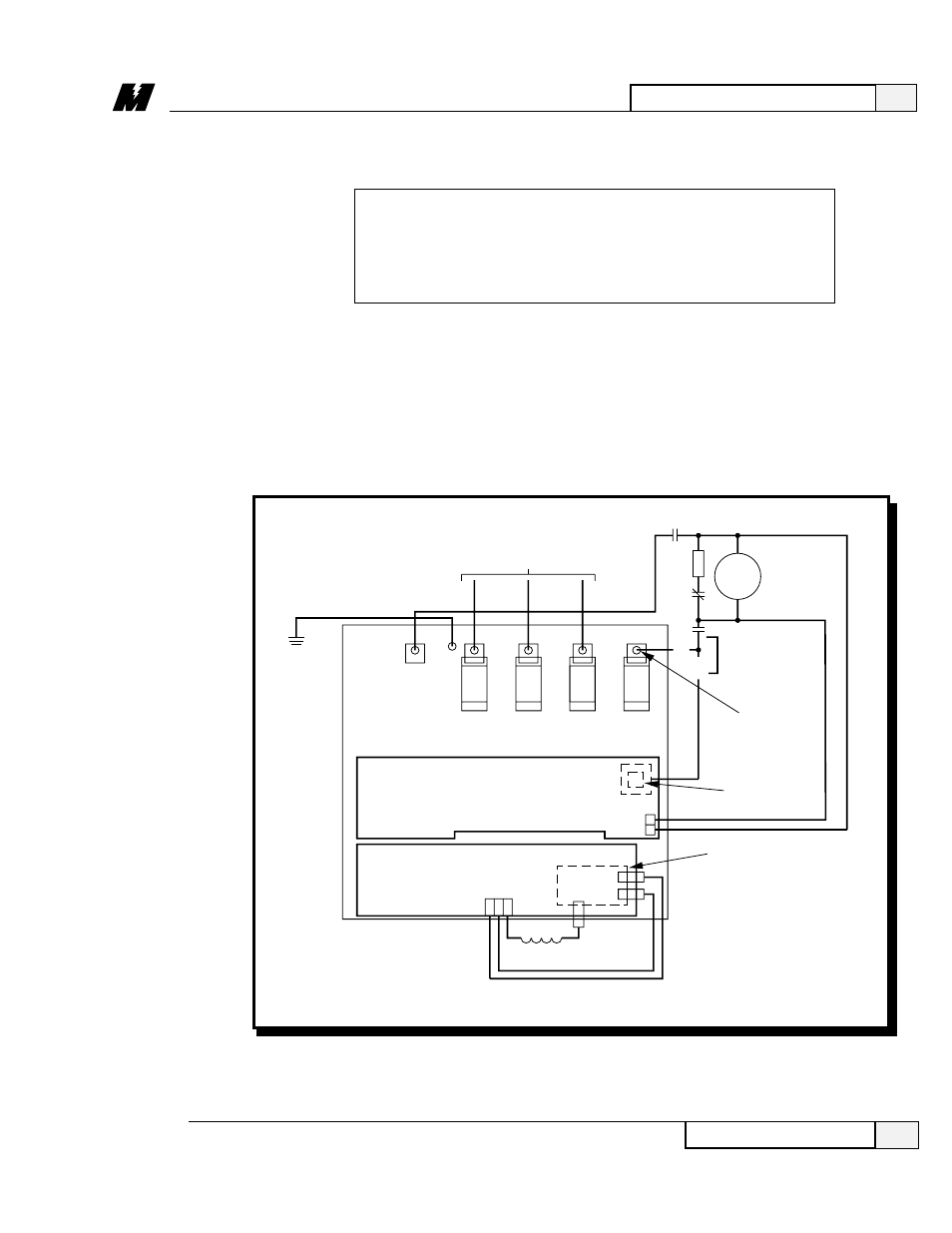
❏ On units rated at 206A armature current (206A Iarm) or less, connect the
three phases of the line from the load side of the isolation transformer or
input circuit breaker to fuses F1, F2, and F3 (marked L1, L2, and L3).
(Refer to Figure 5.) Phase rotation is not important.
Figure 5. Basic Connections for DSD Power Cube –
Ratings up to 206 Amps
GND
OR
3 PHASE 230-460 VAC INPUT POWER
FROM CIRCUIT BREAKER OR
ISOLATION TRANSFORMER.
PHASE ROTATION IS NOT IMPORTANT
K1
DBR
K1
MTR
ARM.
A1
K1
CONNECT TO
ONLY ONE
TERMINAL
PER
APPLICATION
CONNECT HERE
FOR DSD412
ONLY
TB5 (PART OF E5
SCR BUS BAR)
CONNECT
HERE FOR
DSD406
ONLY
FIELD
CONTROL
MODULE
(LOCATED UNDER
FIELD INTERFACE
PCB
)
AC
AC
F2(-)
L2A
L1A
F1(+)
TB4
FIELD INTERFACE PCB (A3)
MOTOR FIELD
F1
F2
(+)
(–)
FRONT VIEW OF POWER CUBE INTERIOR WITH SWING DOOR OPEN
ARMATURE INTERFACE PCB (A2)
(MOUNTED ON SCR BUS BARS)
NEG
+
– 1
2
F2
F1
F3
F4
(DSD
412
ONLY)
LA-2
L1
L2
L3
POS
OR
A2
2
WARNING
The external COAST STOP circuit shown on the
Schematic Diagram MUST BE WIRED to the drive as a
safety consideration in case of microprocessor failure.