Figure 4. shield sheath termination, Installation and start-up, Electrical hook-up – Yaskawa DSD 406 User Manual
Page 20
2
Installation and Start-Up
16
Electrical Hook-Up
3/21/96
●
If the DSD drive is being used in a system application, use a BNC "T"
connector to connect LAN (Local Area Network) coaxial cable to J3 on the
DSD Drive Control PCB.
●
The coaxial cable must ultimately be terminated at both ends by a 93 ohm
termination resistor. (MagneTek part number 05P00034-0586)
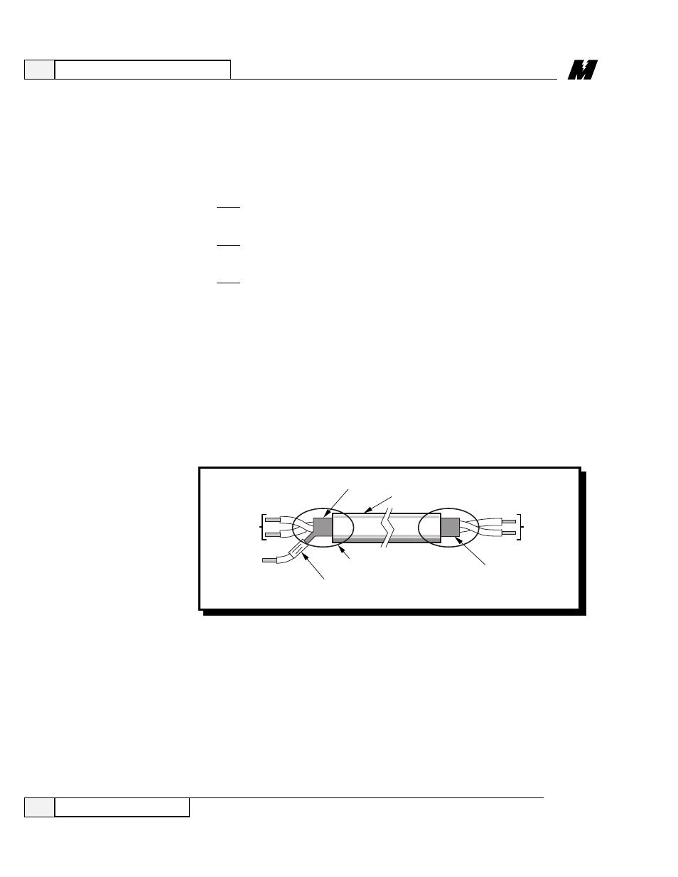
Figure 4. Shield Sheath Termination
●
GND: Recommended conductor size, 2 AWG 600 V vinyl-sheathed for
COPPER wire, 1/0 AWG 600 V vinyl-sheathed for ALUMINUM OR
COPPER CLAD ALUMINUM wire. Recommended torque on the GND
lug is 50 in-lbs.
●
Control Wire Sizing:
TB1: Recommended conductor size, 22-18 AWG 300 V 105°C
vinyl-sheathed wire. Recommended torque is 3.4 in-lbs.
TB3: Recommended conductor size, < 12 AWG 300 V 105°C
vinyl-sheathed wire. Recommended torque is 5 in-lbs.
TB1: Recommended conductor size, 14 AWG 300 V 105°C
vinyl-sheathed wire. Recommended torque is 3.4 in-lbs.
Observe the following when wiring:
●
Separate the leads used for speed reference, feedback, and other low level
signals from those used for the motor armature, field and AC power.
Do not run these two groups in the same conduit or wire trough.
●
Provide shielded and twisted leads as indicated on the Schematic and/or
Interconnection Diagrams. Connect all shields on shielded wire to system
common (not ground) on one end only. Twisted shielded pair wire should be
used for long runs. (Refer to Figure 4 for proper cable preparation.)
TO DSD
406/412
SIGNAL
TERMINALS
TO SHIELD
SHEATH
TERMINAL
SHIELD SHEATH
OUTER JACKET
TO
EXTERNAL
CIRCUIT
DO NOT
CONNECT
WRAP BOTH ENDS
OF SHEATH WITH
INSULATING TAPE
CRIMP
CONNECTION
LA-9