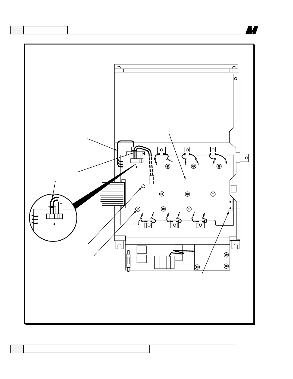
Figure 14. dsd armature interface pcb replacement, Maintenance, Replacing the dsd armature interface pcb – Yaskawa DSD 406 User Manual
Page 90
Advertising
4
Maintenance
86
Replacing the DSD Armature Interface PCB
3/21/96
Figure 14. DSD Armature Interface PCB Replacement
E13
J24
E15
E17
E19
E21
E23
NEG
GND
L1
L2
L3
POS
L2A
L1A
F1 (+)
TB4
A3
ARMATURE INTERFACE PCB
Q4
Q6
Q2
G1
TB5
E12
E10
E8
E6
E4
E2
TB6
TB6
G2
G2
G2
G1
G1
G2
G1
Q1
Q3
Q5
G2
G1
G2
G1
RED
WHT
BLK
6 5 4 3 2 1
(+)
(–)
(N)
MOUNTING SCREW
(9 TOTAL)
ALIGNING
PEG
CONNECTORS FOR
MOTOR ARMATURE
SENSOR FEEDBACK
THERMISTOR
WIRES
CURRENT
SENSOR
LA-101
Advertising
This manual is related to the following products: