Rs-232 connector pin-outs, Mounting the onelink device – Vaddio DocCAM 20 HDBT OneLINK Bridge System User Manual
Page 10
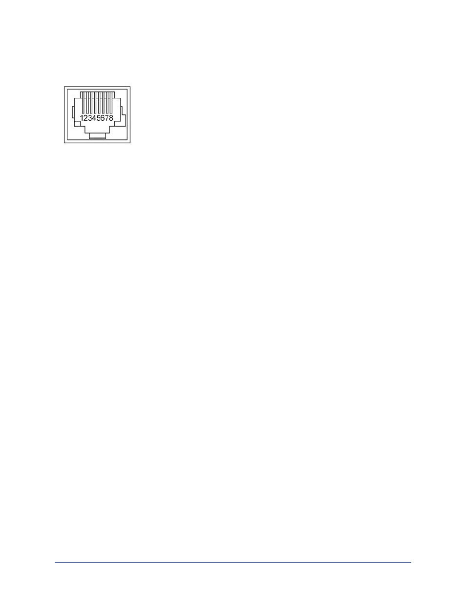
RS-232 Connector Pin-Outs
The OneLINK device passes signals from a third-party device to the connected camera.
OneLINK Receiver - RS-232 Control Port
1. Unused
2. Unused
3. Unused
4. Unused
5. Unused
6. GND
7. RX (from TX of controller)
8. TX (to RX of controller)
OneLINK EZIM - RS-232 Control Port
1. Unused
2. Unused
3. Unused
4. IR GND
5. IR (non-modulated)
6. GND
7. TX (to RX of camera)
8. RX (from TX of camera)
Note
Vaddio recommends following the 568B cabling standard for Cat-5 cabling.
Mounting the OneLINK Device
If you are installing the OneLINK device with a OneLINK EZIM, mount the EZIM with or near the camera.
The Thin Profile Wall Mount for the camera may include mounting holes to attach the EZIM to the
underside of the mount using two 6-32 screws. Connect all required cables during camera installation.
Rack and under-table mounting kits are available for the receiver. Follow the mounting instructions
supplied with the kit.
About Installations Using the Half-Recessed Ceiling Mount
If the connected camera is mounted in Vaddio's Half-Recessed Ceiling Mount, the camera's IR receiver
may have trouble receiving signals from the remote. The mount has an IR receiver that can forward
commands to the camera; this must be powered separately using Power Extension Module 999-1005-
021. Cameras powered by OneLINK devices cannot supply power to the mount's IR receiver.
Complete Manual for the OneLINK Bridge AV Interface
6