Jtag programming header, Jtag programming header –19 – Altera 100G Development Kit, Stratix IV GT Edition User Manual
Page 27
Chapter 2: Board Components
2–19
Configuration, Status, and Setup Elements
September 2010
Altera Corporation
100G Development Kit, Stratix IV GT Edition Reference Manual
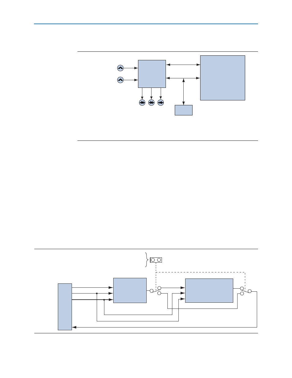
shows the MAX II+Flash FPP configuration.
After a power-up or load event, the MAX II CPLD (U72) automatically configures the
FPGA in FPP mode with either the pre-installed factory .pof file or a user .pof file.
Additionally, three green configuration status LEDs (D39, D40, D41) indicate the
status of the FPP configuration.
After configuration completes, you can determine which .pof image is loaded into the
FPGA by observing the FACTORY_POF LED (D26) or the USER1_POF, USER2_POF,
USER3_POF
LEDs (D19, D20, D25).
JTAG Programming Header
shows the schematic connections for the dedicated JTAG programming
header (J61). This header provides another method for configuring the FPGA (U44)
using an Altera USB-Blaster with the Quartus II Programmer running on a PC. The
MAX II JTAG configuration jumper allows the MAX II CPLD device to be removed
from the JTAG chain so that the FPGA is the only device on the JTAG chain.
Figure 2–5. MAX II+Flash FPP Configuration
Load
Push-Button (S11)
PGM_SEL
Push-Button (S10)
MAX II CPLD
(U72)
FPP Configuration
Flash
Flash
Flash
(U65)
FA
CT
OR
Y_POF LED
(D26)
USER_POF LED
(D19, D20, D25)
MAX_ERR
OR LED
(D38)
Stratix IV GT
FPGA
(U44)
Figure 2–6. JTAG Programming Header
J61
U44
Stratix IV GT
Stratix IV GT
and MAX II
JTAG
Programming
Header
Jumper to remove
MAX II CPLD from
JTAG Programming Header
TDI
TMS
TCK
LAST_TDO
S4GT_TDI
S4GT_TDO
JTAG_TMS
JTAG_TCK
JTAG_TMS
JTAG_TCK
MAX_FPP_TDI MAX_FPP_TDO
U72
MAX II CPLD
9
5
1
3