Board jumpers, Push-button switches, Board jumpers –21 push-button switches –21 – Altera 100G Development Kit, Stratix IV GT Edition User Manual
Page 29
Chapter 2: Board Components
2–21
Configuration, Status, and Setup Elements
September 2010
Altera Corporation
100G Development Kit, Stratix IV GT Edition Reference Manual
lists the board-specific LEDs component references and manufacturing
information.
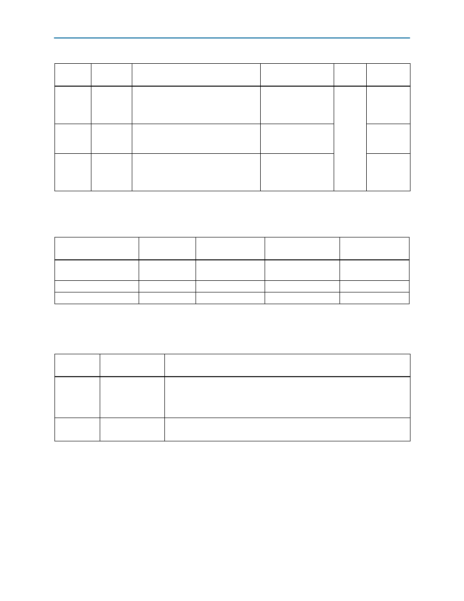
Board Jumpers
Table 2–9
lists the board jumper references, names, and functional descriptions.
Push-Button Switches
Board reference S9 is the CPU reset push-button switch, CPU_RESETn, which is an
input to the Stratix IV GT device. The CPU_RESETn is intended to be the master reset
signal for the FPGA design loaded into the Stratix IV GT device. The CPU_RESETn
signal must be enabled within the Quartus II software for this reset function to work.
Otherwise, the CPU_RESETn acts as a regular I/O pin. When enabled in the Quartus
II software, and then set to logic 1 on the board, this switch resets every register
within the FPGA.
D36
Loading
Green LED. Illuminates when the MAX II
CPLD is actively configuring the FPGA.
Driven by the MAX II System Controller
CPLD.
MAX_LOAD
2.5-V
CMOS
U72.R15
D37
MAX_CONF
Green LED. Illuminates when the FPGA is
successfully configured. Driven by the
FPGA.
MAX_CONF_DONE
U72.H17
D38
Error
Red LED. Illuminates when the MAX II
CPLD EPM2210 System Controller fails to
configure the FPGA. Driven by the MAX II
CPLD EPM2210 System Controller.
MAX_ERROR
U72.T17
Table 2–7. Status LEDs
Board
Reference
LED Name
LED Description
Schematic
Signal Name
I/O
Standard
Other
Connections
Table 2–8. Status LEDs Component References and Manufacturing Information
Board Reference
Device
Description
Manufacturer
Manufacturer
Part Number
Manufacturer
Website
D12–D17, D19, D20, D25,
D26, D27, D36, D37
Green LEDs
Lumex Inc.
SML-LX1206GC-TR
D38
Red LED
Lumex Inc.
SML-LX1206IC-TR
D7
Blue LED
Lumex Inc.
SML-LX1206USBC-TR
Table 2–9. Board Jumpers
Board
Reference
Jumper Name
Description
J41
MAXII BYPASS
■
Jumper installed – the MAX II CPLD device (U72) is included in the JTAG
programming chain.
■
Jumper removed – the MAX II CPLD device (U72) is removed from the JTAG
programming chain.
J40
USB_DISABLEn
■
Jumper installed – the embedded USB-Blaster is disabled.
■
Jumper removed (default) – the embedded USB-Blaster is enabled.